A80
0-4985 INSTALLATION
3T-1
SECTION 3 TORCH:
INSTALLATION
3T.01 Torch Connections
If necessary, connect the torch to the Power Supply. Connect
only the Thermal Dynamics model SL100SV / Automation,
SL100 / Mechanical or SL60 / Manual Torch to this power
supply. Maximum torch leads length is 100 feet / 30.5 m,
including extensions.
WARNING
Disconnect primary power at the source
before connecting the torch.
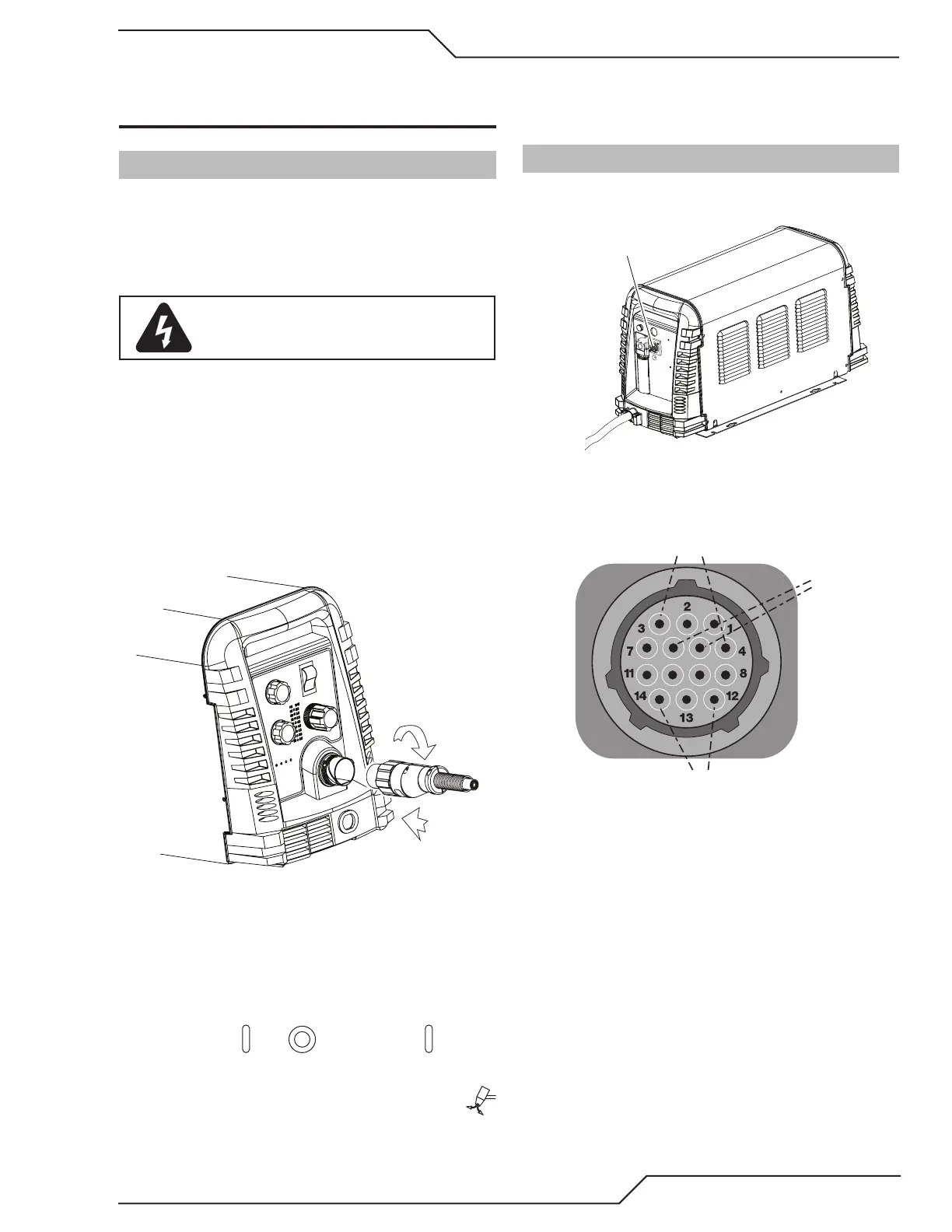
1. Align the ATC male connector (on the torch lead)
with the female receptacle. Push the male con-
nector into the female receptacle. The connectors
should push together with a small amount of pres-
sure.
2. Secure the connection by turning the locking nut
clockwise until it clicks. DO NOT use the locking nut
to pull the connection together. Do not use tools to
secure the connection.
1
2
Art # A-07885
Connecting the Torch to the Power Supply
3. The system is now ready for operation.
Check Air Quality
To test the quality of air:
1. Put the ON / OFF switch in the ON (up) posi-
tion.
2. Put the Function Control switch in the SET
position.
3. Place a welding lter lens in front of the torch and
turn ON the air. Do not start an arc!
Any oil or moisture in the air will be visible on the lens.
3T.02 CNC Connection
1. Locate the interface connection port on the rear of
the power supply.
utomation Interface
le Port
2. Note the pin-out of the connector and that the
customer supplied connector matches.
Start / Stop
Signal
Cutting Machine
OK to Move
Arc
V
There are three options for Divided Arc Voltage
signal supplied from the automation interface PCB.
This is selected by connecting the black Jumper Plug
on the P1 connector as follows:
Arc voltage / 16.67 Jumper not installed
Arc voltage / 30 Jumper Pins 1 & 2 . This is the factory
default position of the jumper
Arc voltage / 50 Jumper Pins 2 & 3