A80
INSTALLATION 0-4985
3T-2
+12VDC
PCB4
AUTOMATION
INTERFACE PCB
}
OK-TO-MOVE
FULL FEATURED AUTOMATION INTERFACE PCB OPTION
(+)
}
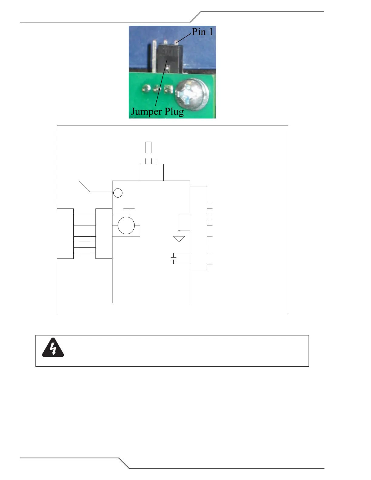
To configure DIVIDED ARC VOLTS signal output
No jumper installed for ARC VOLTS /16.67
Jumper pins 1 & 2 for ARC VOLTS / 30
Jumper pins 2 & 3 for ARC VOLTS / 50
K1
To -V OUT 1
on PCB1
}
/START / STOP
**
}
DIVIDED ARC VOLTS
(+)
(-)
(W/ 100K IN SERIES (2))
(-)
*
ARC VOLTS
J1J1
1
2
3
4
5
6
7
8
J3J3
1
2
3
P10P10
1
2
3
4
5
6
7
8
E1E1
K1K1
J2J2
2
3
4
5
6
7
8
9
10
11
12
13
14
1
Art # A-09819_AB
WARNING
This divided arc voltage output signal is positive. Its common (-) is referenced to the work lead
(ground). Using this on a height control expecting a negative signal and whose positive input
is grounded may damage the divided arc voltage circuit.
3. Connect CNC to the power supply.