A80
0-4985 OEPRATION
4T-1
SECTION 4 TORCH:
OPERATION
4T.01 Machine and Automated Torch
Operation
Cutting With Machine or Automated Torch
These torches are activated by remote control pendant
or by a remote interface device such as CNC.
1. To start a cut at the plate edge, position the center
of the torch along the edge of the plate.
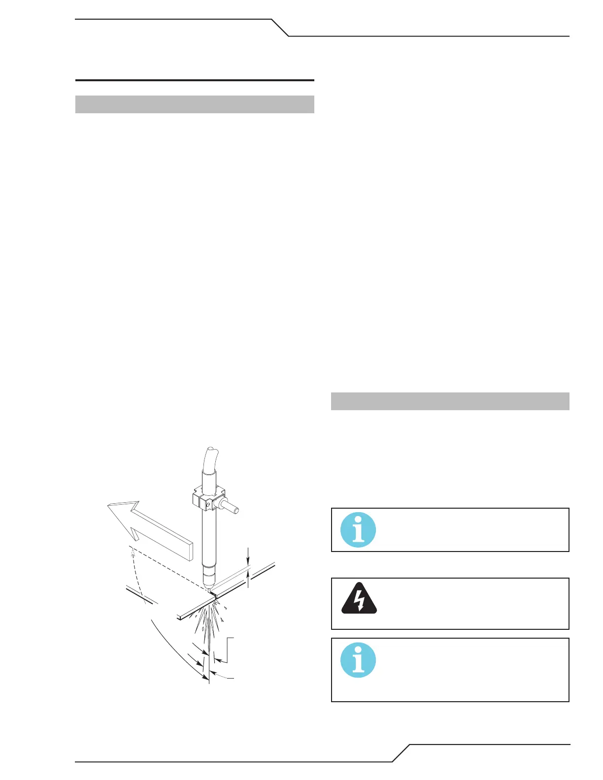
Travel Speed
Proper travel speed is indicated by the trail of the arc
which is seen below the plate. The arc can be one of
the following:
1. Straight Arc
A straight arc is perpendicular to the workpiece
surface. This arc is generally recommended for the
best cut using air plasma on stainless or aluminum.
2. Leading Arc
The leading arc is directed in the same direction as
torch travel. A ve degree leading arc is generally
recommended for air plasma on mild steel.
3. Trailing Arc
The trailing arc is directed in the opposite direction
as torch travel.
Stando Distance
Straight Arc
Trailing Arc
Leading Arc
Direction of Torch Travel
A-02586
Automation and Machine Torch Operation
For optimum smooth surface quality, the travel speed
should be adjusted so that only the leading edge of the
arc column produces the cut. If the travel speed is too
slow, a rough cut will be produced as the arc moves from
side to side in search of metal for transfer.
Travel speed also aects the bevel angle of a cut. When
cutting in a circle or around a corner, slowing down
the travel speed will result in a squarer cut. The power
source output should be reduced also. Refer to the
appropriate Control Module Operating Manual for any
Corner Slowdown adjustments that may be required.
Piercing With Machine or Automated Torch
To pierce, the arc should be started with the torch
positioned as high as possible above the plate while
allowing the arc to transfer and pierce. This stando
helps avoid having molten metal blow back onto the
front end of the torch.
When operating with a cutting machine, a pierce or
dwell time is required. Torch travel should not be en-
abled until the arc penetrates the bottom of the plate.
As motion begins, torch stando should be reduced
to the recommended 1/8 - 1/4 inch (3-6 mm) distance
for optimum speed and cut quality. Clean spatter and
scale from the shield cup and the tip as soon as pos-
sible. Spraying or dipping the shield cup in anti - spatter
compound will minimize the amount of scale which
adheres to it.
4T.02 Automation Torch Parts Selection
Check the torch for proper consumable parts. The
parts supplied in the torch may not be correct for the
operator’s chosen amperage level. The torch parts must
correspond with the type of operation.
Torch parts:
Shield Cup, Cutting Tip, Electrode and Starter Cartridge
NOTE!
Refer to Sections 4T.08 and following for ad-
ditional information on torch parts.
Change the torch parts for a dierent operation as follows:
WARNING
Disconnect primary power at the source
before assembling or disassembling torch
parts, or torch and leads assemblies.
NOTE!
The shield cup holds the tip and starter car-
tridge in place. Position the torch with the
shield cup facing upward to keep these parts
from falling out when the cup is removed.