Manual 0-2582 17 SERVICE TROUBLESHOOTING
13. Faulty Gate Drive PC Board (refer to Appendix XI,
36 VAC Circuit Diagram)
Measure for 36 VAC on Gate Drive PC Board from
J9-1 to J9-3.
• If voltage is not present, replace the Gate Drive
PC Board
• If voltage is present,, replace Logic PC Board
C. AC indicator ON, TEMP indicator ON, System
will not pilot
1. Air flow through unit is restricted
a. Provide adequate air flow (Refer to Operating
Manual 0-2581, Section 3.02)
2. Exceeded duty cycle of Power Supply
a. Wait for fans to cool unit and refer to Operating
Manual 0-2581, Section 2.03, for proper Duty
Cycle
3. Faulty Fan or Logic PC Board
Measure for 115 VAC on the Logic PC Board from
J2-2 to J2-8 and J2-3 to J2-9.
• If voltage is correct, replace Fan Assembly
• If voltage is incorrect, replace Logic PC Board
4. Faulty temperature circuit
a. Check temperature circuit per Section 4.09-F;
repair as necessary
D. AC indicator ON; TEMP indicator ON; System
will pilot (RUN/SET switch must be in RUN)
1. Open Ribbon Cable or faulty FET/Heatsink Assembly
Check continuity on Logic Ribbon Cable from J4-
10 (Logic PC Board) to J6-10 (FET/Heatsink As-
sembly)
• If cable has open, replace ribbon cable
• If cable has continuity, replace FET/Heatsink
Assembly
2. Defective Logic PC Board
On Logic PC Board jumper J4 pin 9 to J4 pin 10
a. If TEMP indicator stays ON then replace Logic
PC Board
E. AC indicator ON; TEMP indicator OFF; No gas
flow; GAS and DC indicators OFF
1. RUN/SET switch in RUN position
a. Switch to SET position
2. Gas supply not connected to unit
a. Connect to gas supply
3. Gas supply not turned on
a. Turn gas supply on
4. Faulty RUN/SET switch
a. Check continuity
5. Faulty gas solenoid circuit
a. Test gas solenoid circuit per Section 4.09-G; re-
pair as necessary
F. AC indicator ON; GAS indicator OFF; Gas flows;
DC indicator OFF
1. Gas pressure to low
a. See torch manual for operating pressures
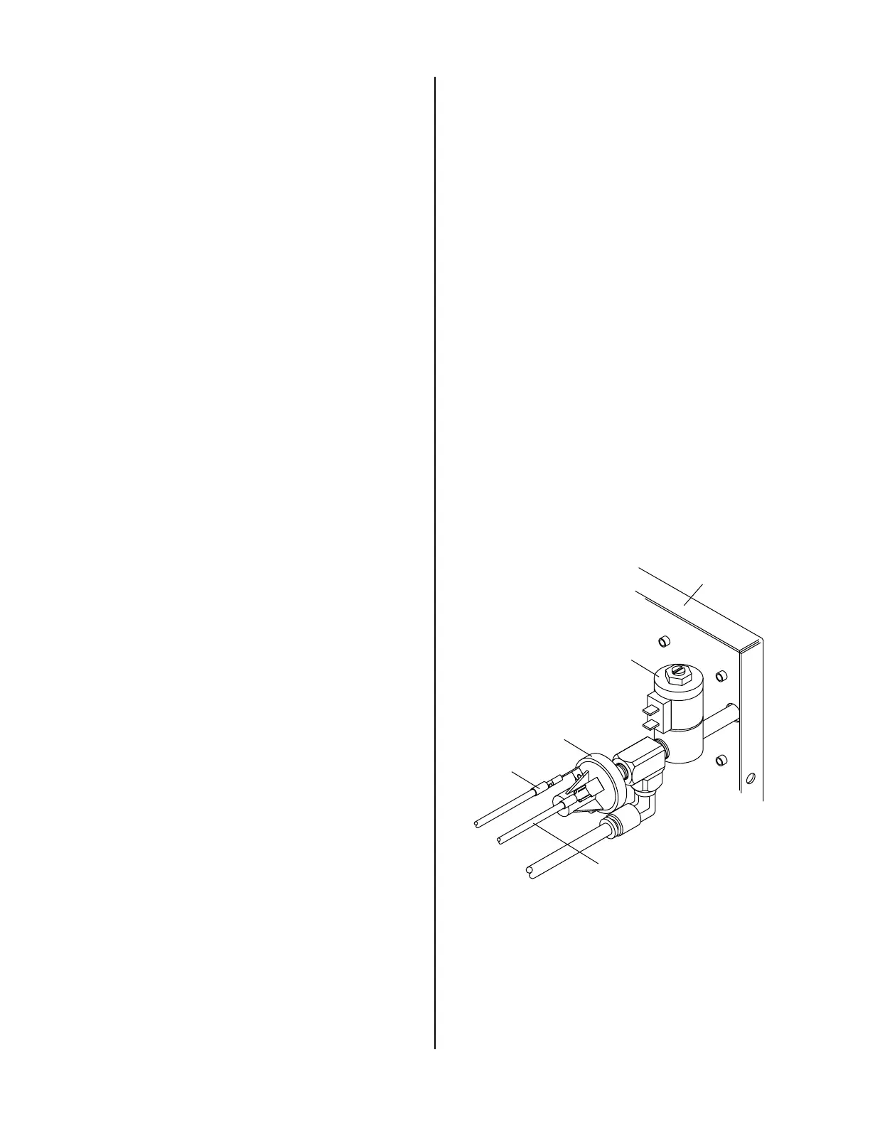
2. Faulty pressure switch
Measure for DC voltage from wire #51 to wire #50
at the gas pressure switch at the rear of the Rear
Panel Assembly.
a. If 12vdc and pressure is above 50 PSI, replace
gas pressure switch.
Wire #51
Wire #50
Gas Pressure Switch
Rear Panel
Gas Solenoid
A-01184
5. Faulty Wiring or Logic PC Board
Check for DC voltage from Logic PC Board J2-13
to TP1 (GND)
• If less than a volt, replace Logic PC Board
 Loading...


