Manual 0-2582 27 SERVICE TROUBLESHOOTING
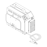
A-01401
Pilot Output PC Board
E29
E7
Top
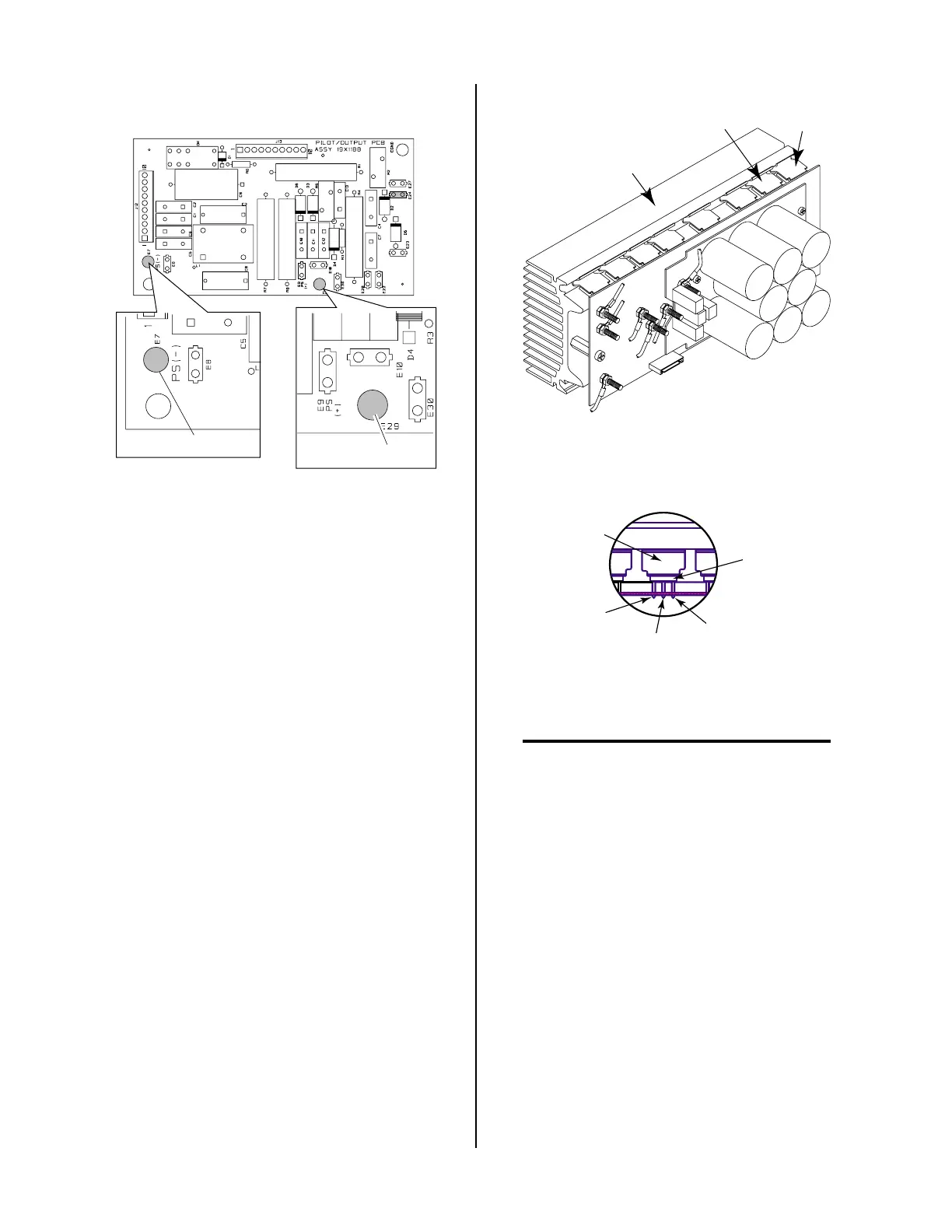
2. FET/Heatsink Output Diode Checks
Remove input power from the unit.
Isolate each FET/Heatsink Assembly by removing the
red wire #12 at E18 and the black wire #11 at E17 on
each FET/Heatsink Assembly. With an ohmmeter set
on the diode range, check between the two output
studs, E17 (- output) to E18 (+ output). This should
indicate a diode drop in one direction and open in the
other.
If the checks indicate open or shorted in both direc-
tions then the faulty Fet/Heatsink Assembly should
be replaced.
3. MOSFET Resistance Checks
The Power Supply contains two identical FET/
Heatsink Assemblies. On each assembly there are two
MOSFET devices that must be checked. Use an ohm-
meter to check for the proper resistance of the
MOSFET's per the following procedure:
a. Locate Q1 and Q6 on the FET/Heatsink Assembly.
A-01414
Q1
FET/Heatsink and
Capacitor PC Board
Assembly
Q6
b. Place the meter (+) lead on gate lead of Q1 and
meter (-) lead on source lead of Q1. The meter
should indicate approximately 2.5K ohms.
A-00553
MOSFET
Spring
Clip
Gate
Drain
Source
c. Place the meter (+) lead on drain lead of Q1 and
meter (-) lead on source lead of Q1. The meter
should indicate >100K ohms.
NOTES
Make measurements near the body of each
MOSFET.
Be sure that the meter lead probes penetrate the
protective coating on the MOSFET.
d. Place the meter (+) lead on drain lead of Q1 and
meter (-) lead to the heatsink. The meter should
indicate >1 meg ohms.
e. Place the meter (+) lead on gate lead of Q6 and
meter (-) lead on source lead of Q6. The meter
should indicate approximately 2.5K ohms.
f. Place the meter (+) lead on drain lead of Q6 and
meter (-) lead on source lead of Q6. The meter
should indicate >100K ohms.
 Loading...


