ULTRA-CUT 200 XT
A-46 APPENDIX Manual 0-5304
APPENDIX 25: ADVANCED TROUBLESHOOTING
System Overview
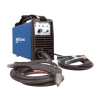
The Auto-Cut 200 & 300 XT, PAK200i & Ultra-Cut 100, 200,
300 & 400 XT power supplies include one, two or three
inverter modules (IM). Each IM may have either 1 or 2
inverter sections designated A or B sections. The IMs are
mounted one over the other numbered from bottom to top.
The sections are also designated from bottom to top with
section A being on the bottom of each module. An IM with
one section is considered to be a ½ or “partial” module with
the upper or “B” section missing. ½ modules are used with
the 200A & 300A power supplies and will always be in the
middle position. IMs with 2 sections are considered to be
“full” modules.
Each inverter section can supply up to 67A but does not do
so in all configurations:
A 400A unit uses 6 sections. 400A / 6 = 66.67A per section.
A 300A unit uses 5 sections. 300A / 5 = 60A per section.
A 200A unit uses 3 sections. 200/3 = 66.67A per section.
A 100A unit uses 2 sections. 100/2=50A per section.
Unit congurations.
With the exception of the AC 200 XT and PAK200i all other
units have the same chassis with room for up to 3 IMs. The
unused areas have blank panels filling the empty locations
which are required for proper air flow. A 100A system uses
1 full IM; 200A uses 1 and ½ modules with a full module in
the bottom location and a ½ module in the middle position.
A 300A unit has full modules top and bottom with the ½
module in the middle location. The AC 200 XT and PAK200i
have only the bottom and middle locations for IMs. An in-
ternal Arc Starter and Gas Control are located in the place
of the 3rd or upper IM.
Inverter module cooling.
The power semiconductors of the inverter modules are liq-
uid cooled allowing us to get more power in a smaller area
and at lower cost. Each IM has a liquid cooled heatsink or
“cold plate” shared by the 2 inverter sections. The magnetic
components, transformers and inductors, are air cooled and
mounted on the back side of the IMs where they are exposed
to high volumes of air flow from the cooling fans whose air
also cools liquid coolant in the radiator or heat exchanger.
It is important that lower right side panel be in place or the
air flow will not be proper for cooling the magnetics.
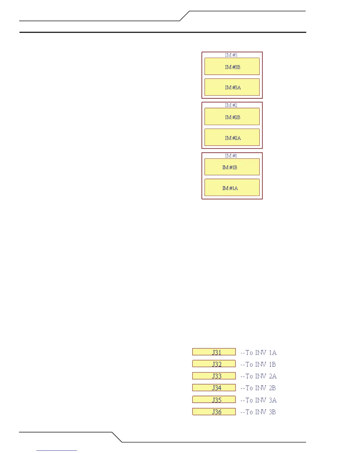
Inverter control.
The inverter sections are operated as separate inverters
whose outputs are connected in parallel. They are controlled
independently from the Command and Control Module
(CCM) which is the “brains” of the system. Each inverter sec-
tion has a separate ribbon cable connected to it coming from
the CCM which has 6 connectors, J31 – J36 corresponding
Art # 12299
Art # 12300

 Loading...