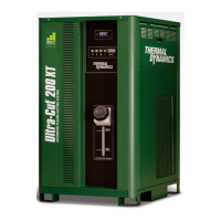
ULTRA-CUT 200 XT
Manual 0-5304 OPERATION 4-15
3. Water Shield
• Normallyusedwithnitrogen.
• Providesverysmoothcutsurface.
• Reducessmokeandheatinputtotheworkpiece.
• EffectivewhenusedwithN2upto2inch(50mm)maximummaterialthickness.
• Tapwaterprovideslowoperatingexpense.
Operational Suggestions
1. Wait four minutes before setting the ON/OFF switch to OFF after operation. This allows the cooling fans to run to dissipate
operating heat from the power supply.
2. For maximum parts life, do not operate the pilot arc any longer than necessary.
3. Use care in handling torch leads and protect them from damage.
4. When using water as the shield note the following:
• Usecleandrinkingqualitytapwatertohelppreventparticulatebuild-upwithinthesystemwatershieldplumbing.
• Particulatecontaminationandbuild-upcancausereducedconsumablepartslifeandprematuretorchfailure.
• Acartridgetypeparticulatewaterltermayhelpachieveoptimumcuttingperformance.
4.11 CCM Status Codes
NOTE!
See the Appendix for Advanced Troubleshooting
On start-up and during operation, the power supply control circuitry performs various tests. If the circuitry detects a condition
requiring operator attention, the status display on the front panel shows a 3 digit number code preceded by either letter “E”
(currently active fault) or letter “L” (last or latched fault) meaning a fault occurred during the process but is not currently active.
Some conditions can be active indefinitely, while others are momentary. The power supply latches momentary conditions; some
momentary conditions can shut down the system. The indicator may show multiple conditions in sequence; it is important to
recognize all possible conditions that may be displayed.
NOTE!
These tables cover units up to 400A, Lower current units won’t have all the inverter
sections referred to in Group 2. Codes for those sections should not appear.
 Loading...
