ULTRA-CUT 200 XT
3-44 INSTALLATION Manual 0-5304
7. Slide the ohmic clip over the shield cup if using ohmic torch height sensing.
8. Connect the wire lead from the height finder to the ohmic clip if using ohmic torch height sensing.
Art # A-03393_AB
NOTE!
Ohmic height sensing is not recommended with water shield. Water on the
plate interferes electrically with the ohmic sensing circuit.
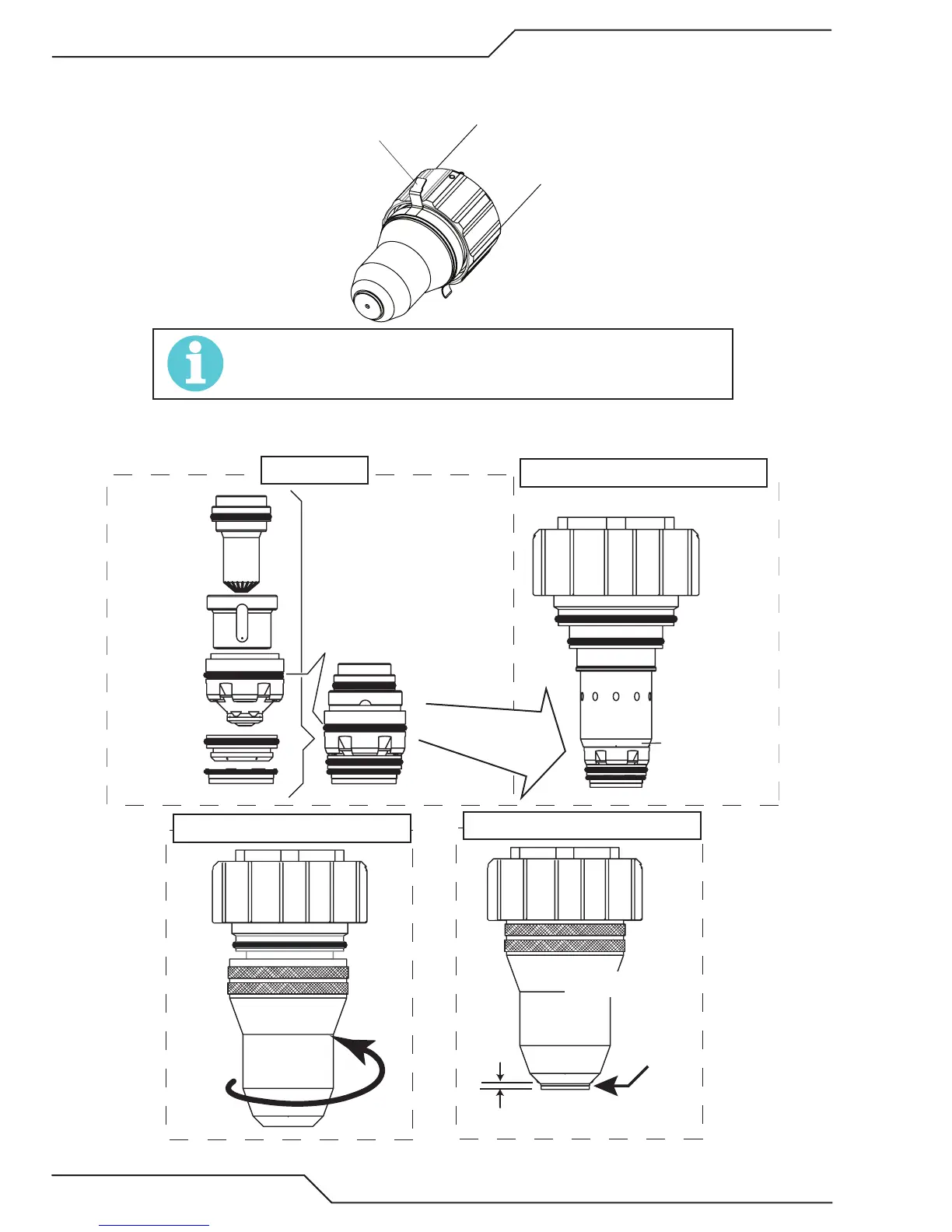
30 - 100 Amp Parts Assembly
Cartridge Covers
O-Ring
on Torch Tip
Shield Cap Protrudes
0.063-0.083" (1.6 - 2.1 mm)
Electrode
Plasma Gas
Distributor
Tip
Shield Gas
Distributor
Shield Cap
O-Ring
on Tip
1: Stack Parts
2: Press Cartridge onto Stacked Parts
4: Check Shield Cap Protrusion
Art # A-04873
No Gaps
Between Parts
3: Thread Shield Cup onto Cartridge
Shield Cap
Shield Cup
Installing Assembled Cartridge Onto Torch Head

 Loading...