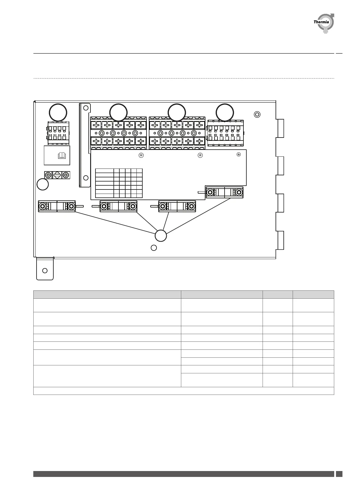
9.2 Outdoor terminal connections
Inputs for the outdoor unit according to the picture and table below
X5
Electrical heater
X3
Compressor
X4
Control voltage
L1 L2 L3 N L1 L2 L3 N
L-
O
N
N
ERR
2,6 kW L1 N PE
3,0 kW L2 PEN
3,2 kW L3 PEN
5,6 kW L1 L2 N PE
5,8 kW L1 L3 PEN
6,2 kW L2 L3 PEN
8,8 kW L1 L2 L3 PEN
BUS
X2
1
5
6
2 3 4
5V A B
T
1 2 3 4
X2
BUS
X5
Electric heater
X3
Compressor
X4
Control voltage
5V: 5V (not in use) Connected load & terminal assign-
ment
L1 -
A: Connect to D+ on indoor unit 2,6 kW: L1, PE L2 ON
B: Connect to D- on indoor unit 3,0 kW: L2, PE L3 ERR
Earth: GND (ground) 3,2 kW: L3, PE N L: Power supply
5: Earth terminal for shielding the BUS cable (Note below) 5,6 kW: L1, L2, PE PE N: Power supply
5,8 kW: L1, L3, PE PE: Power supply
Note: BUS cable must be UV-resistant twisted pair data/tele-
phone shielded cable, 0.75mm², 4 wire, maximum length 30m
6,2 kW: L2, L3, PE
8,8 kW: L1, L2, L3, PE
(Recommended connection)
6: Cable strain relief
Installation Guide Athena
Thermia AB AWAT01IGCG0102
45
 Loading...