Wiring
Serial Communications
AC Power
If the optional AC power board is installed, the gauge may be operated using voltages
from 100 to 240 VAC.
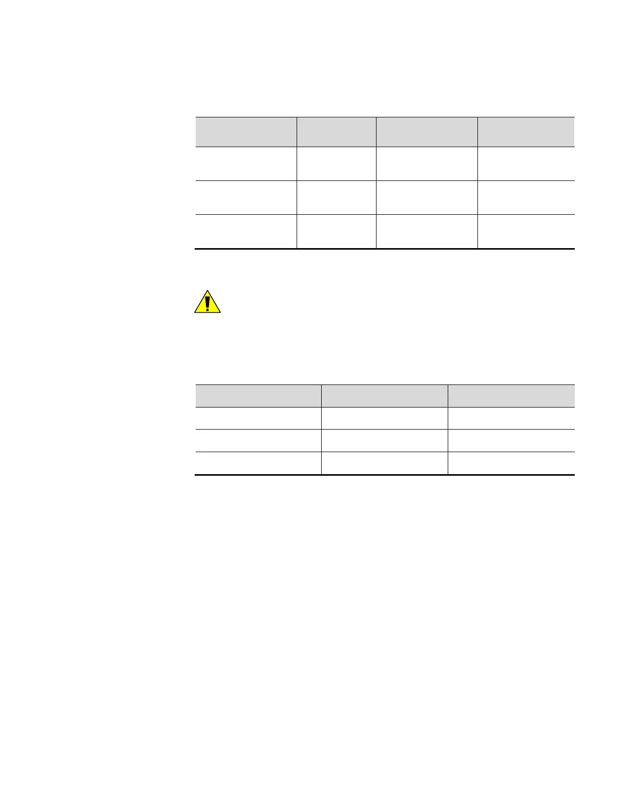
Table 4-2. Site AC Power Wiring
Signal / Connector
MS2011DUR
Detector
MS2011T
Transmitter
MS2011DUI
(Integrated)
AC Power, Line L (Pin 3)
Line
(PS-PCA J8 Pin 1)
Line
(PS-PCA J8 Pin 1)
AC Power, Earth Ground E (Pin 2)
Earth
(J8 Pin 2)
Earth
(J8 Pin 2)
AC Power, Neutral N (Pin 1)
Neutral
(PS-PCA J8 Pin 3)
Neutral
(PS-PCA J8 Pin 3)
If both AC and DC input power are supplied to the detector, the detector will draw
power from whichever source provides the higher DC voltage.
Caution: For reliable operation, and to maintain safety approval, only replace
the F2 fuse on the AC power board with an approved fuse. Reference the
installation wiring drawings.
The AC power board contains color-coded wires. Determine the function of the wire
by consulting the color-coding listed below.
Table 4-3. Site AC Power Wire Color-Coding
Signal / Standard USA International
Hot Black Brown
Neutral White Blue
Ground Green Green with Yellow Stripe
Serial
Communications
The gauge provides one RS232 single-drop and one RS485 multi-drop serial interface.
Screw-terminal connectors for both ports are located on the Main CPU board.
Both ports are configurable and able to display measurements, and both provide
independent access to the measurement readings and software functions. For
information on configuring communications, refer to the DensityPRO Measurement
System User Guide (p/n 1-0702-016).
4-4 DensityPRO Installation Manual Thermo Scientific