Wiring
Standard Wiring
RS485 Detector to
Transmitter Wiring
Connect the detector’s RS485 communication cable between the remote detector unit
(MS2011DUR) and the transmitter unit (MS2011T) as shown in the table below.
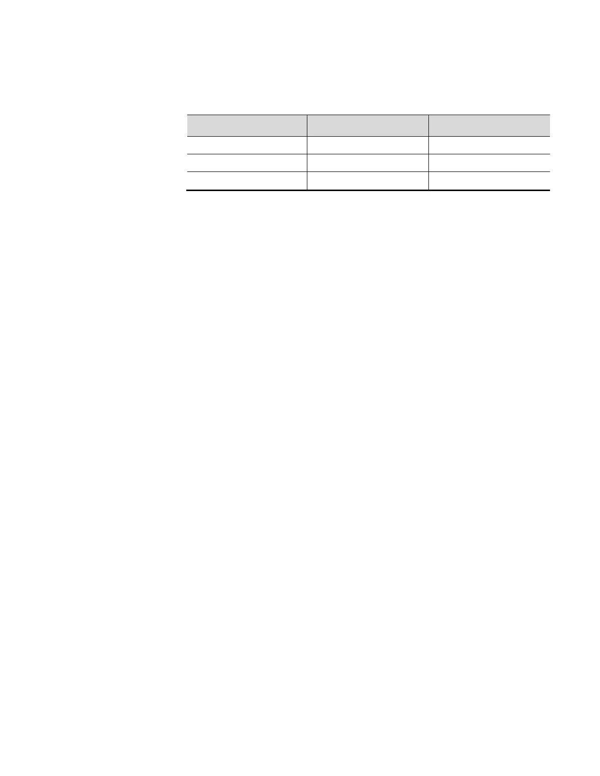
Table 4-4. RS485 Detector to Transmitter Wiring
Signal / Connector MS2011DUR Detector MS2011T Transmitter
485A 485A (Connector Pin 7) 485A (PS-PCA J3A Pin 1)
485B 485B (Connector Pin 8) 485B (PS-PCA J3A Pin 2)
GND GND (Connector Pin 9) GND (PS-PCA J3A Pin 3)
Initial Setup for
Party-Line
Communications
To communicate with multiple gauges via RS485 party line, each unit must be
assigned a unique unit identification number so it can be addressed individually. By
default, all gauges are assigned unit number one (1).
To assign a unique unit number to each gauge, you must be able to communicate with
each one individually. Disconnect each gauge from the party line in turn and
communicate with the disconnected gauge directly. Alternatively, remove power from
all gauges except one and assign a unit number to the powered gauge. Repeat this
procedure for the remaining gauges.
If trouble arises when using another device on the RS485 chain, verify that the device
is properly terminated for its position on the chain. To terminate a device, connect a
120-ohm resistor between its RS485 +/- data terminals. Never terminate more than the
first and last device in the chain.
Standard Wiring
USB
The Main CPU PCA includes a USB port, which allows the user to connect to the
system using a type A Male to Mini 5-pin Male USB cable. Operators should ensure
the area is non-hazardous before connecting or disconnecting the USB cable.
Ethernet
Each DensityPRO unit includes a 10 Base-T minimum Ethernet port on the Main
CPU PCA. Operators should ensure the area is non-hazardous before connection or
disconnecting the Ethernet cable.
Thermo Scientific DensityPRO Installation Manual 4-7
 Loading...