SAFE 2010/MaxiSAFE 2010
INSTRUCTION MANUAL
Page 13 of 35
81-09-IM.doc
1. Bring the front window to the lowest position.
2. Disconnect the power.
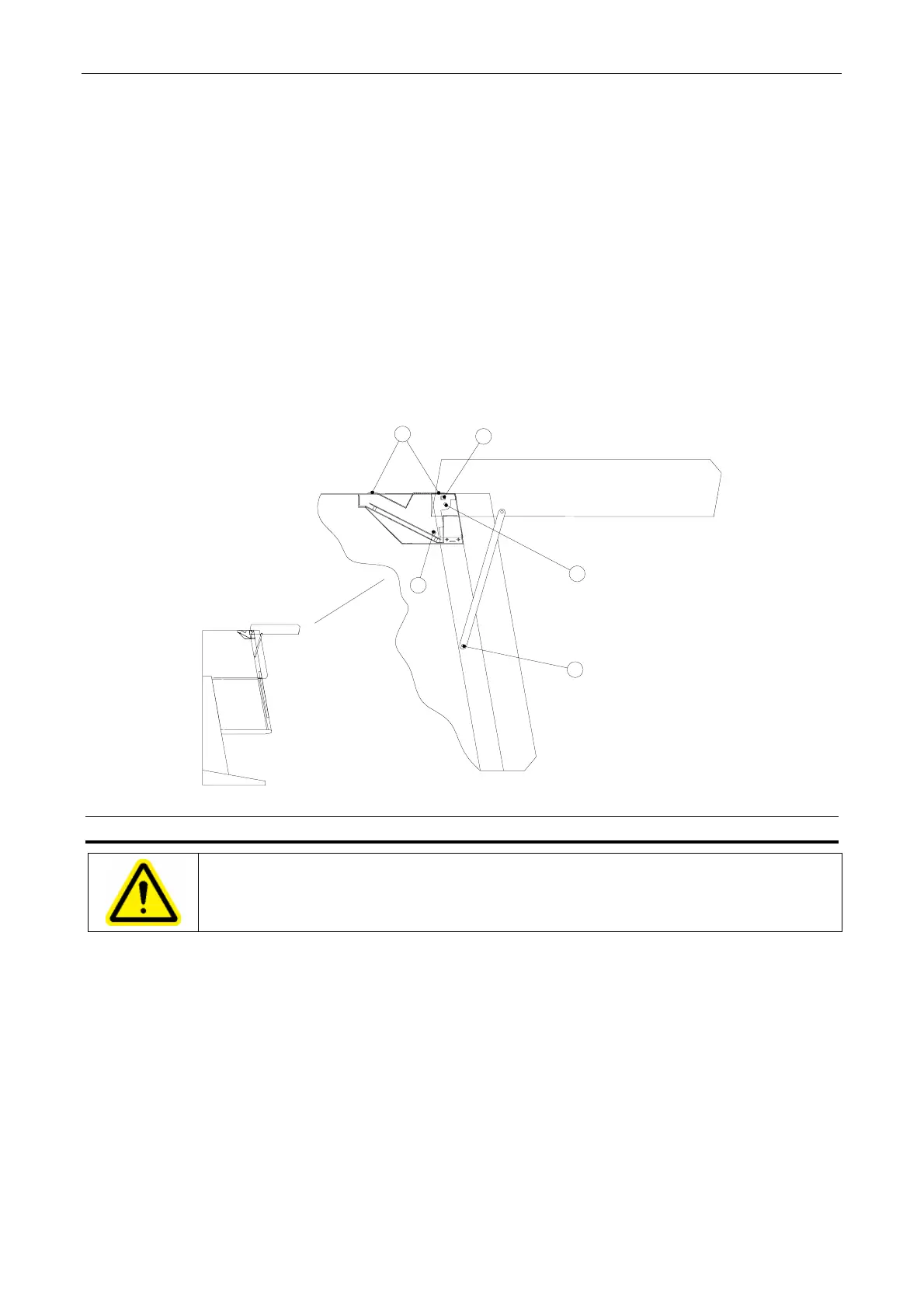
3. Remove the protective cover from the fuses (4 screws) - position 1 figure 4.
4. Pull out the plug - position 2 figure 4 - for the flat cable for the display PCB on the control
PCB.
5. Disconnect the protective earth wire - position 3 figure 4.
6. Unscrew the screws for the gas spring - position 4 figure 4.
7. Unscrew the screws for the front shield - position 5 figure 4.
8. Remount the front shield in the reverse order, and continue with section 6.2 step 1 below:
1
2
3
4
5
Figure Fejl! Ukendt argument for parameter.. How to dismount the front shield.
6.2. Preparation
WARNING
The installation site for the unit must be draught-free and should be selected so that
frequent passing of people in front of the work opening is avoided.
1. The tabletops of stainless steel are mounted over the trough.
2. Adjust the levelling screws to assure that the tabletop is in horizontal position and levelled.
3. Valves for gases or vacuum are installed in the side windows. A qualified technician must
make the connections for the supply.
4. For connection of the exhaust air to the exhaust air systems, special precautions which must
be discussed with the cabinet supplier, must be taken.
5. The armrest has to be mounted over the perforated holes.