Page 6 / 35
INSTRUCTION MANUAL
SAFE 2010/MaxiSAFE 2010
81-09-IM.doc
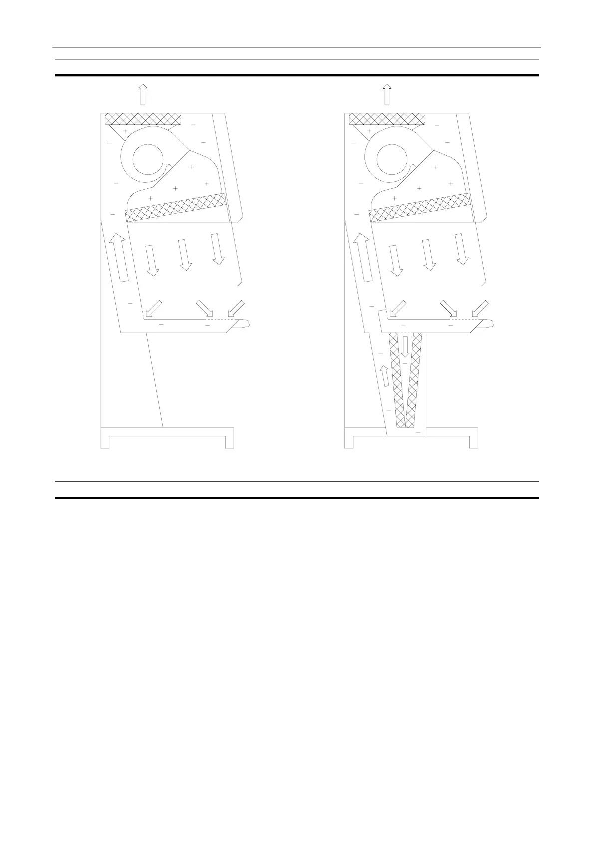
3.4. Airflow diagram
Figure Fejl! Ukendt argument for parameter..
SAFE 2010
Figure Fejl! Ukendt argument for parameter..
MaxiSAFE 2010
3.5. Design
The safety cabinet consists of:
• Fan and filter compartment and return air duct (double back wall) made of polyester coated
sheet steel.
• Support stand made of polyester coated sheet steel and equipped with levelling feet.
• Work chamber with tabletop and trough in stainless steel (AISI 304).
• Side windows and sliding front window all in safety glass.
• Internal ventilation system with negative pressure plenum.
• Microprocessor control and supervision system.
The work chamber is formed by the ceiling (main HEPA filter), side windows, back wall with
installation zones, tabletop and trough; the front is partly closed by the double-action, sliding front
window; the work opening is situated below the front window.
• The outlet opening of the main HEPA filter cover the entire ceiling surface thus giving an
extremely uniform airflow.