Table 22. Removal steps of base cover and PC Card/ExpressCard (or ExpressCard/Smart
Card) bezel assembly (continued)
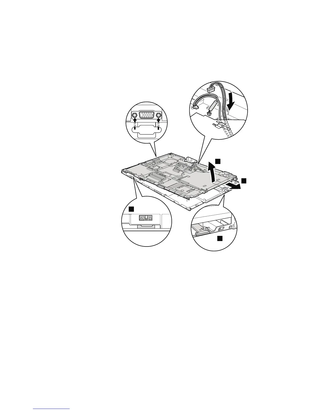
Attention: Before step 7, be sure that the Serial Ultrabay Enhanced device
eject lever has not popped out. It must be housed in its position as shown in the
figure a.
a
7
8
b
When installing: Check the position of the wireless switch b, and firmly fit
the structure frame into the base cover.
114 ThinkPad R500 Hardware Maintenance Manual