15
Two-, and Three-Channel Stepper Motor Controller
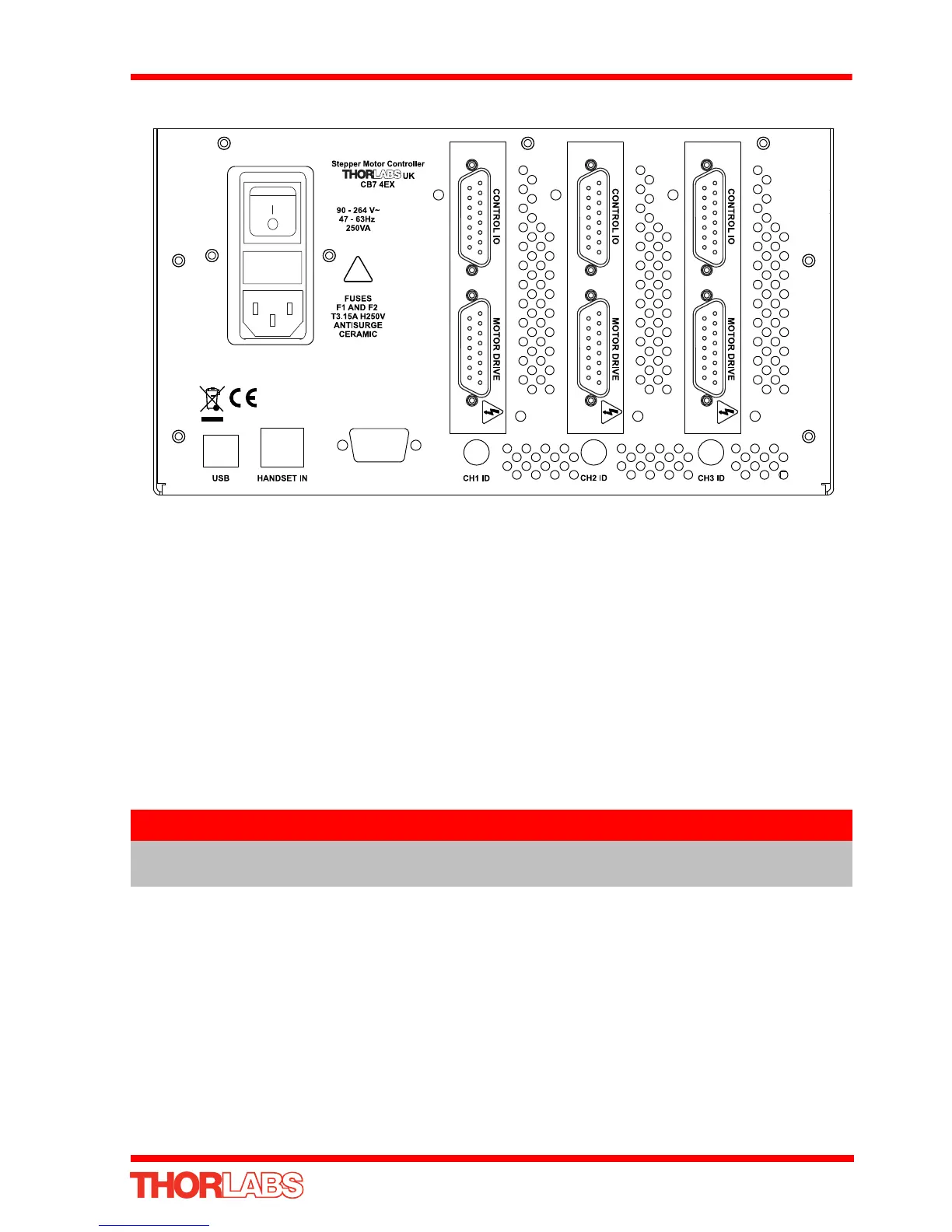
3.3.4 Rear Panel Connections
Fig. 3.1 Rear panel connections
MOTOR DRIVE - (15-Pin D-Type, Female) Provides connection to the actuator.
This connector provides all phase current drive and encoder feedback connections to
drive a range of encoded and non-encoded stepper motors - see Section A.3.
CONTROL I/O
- (15-Pin D-Type, Female) The ‘CONTROL I/O’ connector exposes a
number of electrical signals useful for external control. It is possible to configure a
particular controller to resp ond to trigger inputs, generate trigger outputs or bo th
respond to and generate a trigger output - see Section 5.3.3. Motor jogging lines can
be used to jog the motor in both forward and reverse directions from a remote handset
(Jogging parameters (e.g. jog distance) are set via the GUI panel - see Section 5.3.1.).
USB - USB port for system communications.
HANDSET IN - Provides connection for the MJC001 Joystick - see Section 4.9. and
Section A.2.
INTERCONNECT - (9-Pin D-Type, Male) For Future Use. No function at present.
CH ID - For channel selection when using the MJC001 joystick - see Section 4.9.
Note
The USB cable length should be no more than 3 metres unless a powered
USB hub is being used.