48
Appendix A Rear Panel Connector Pinout Details
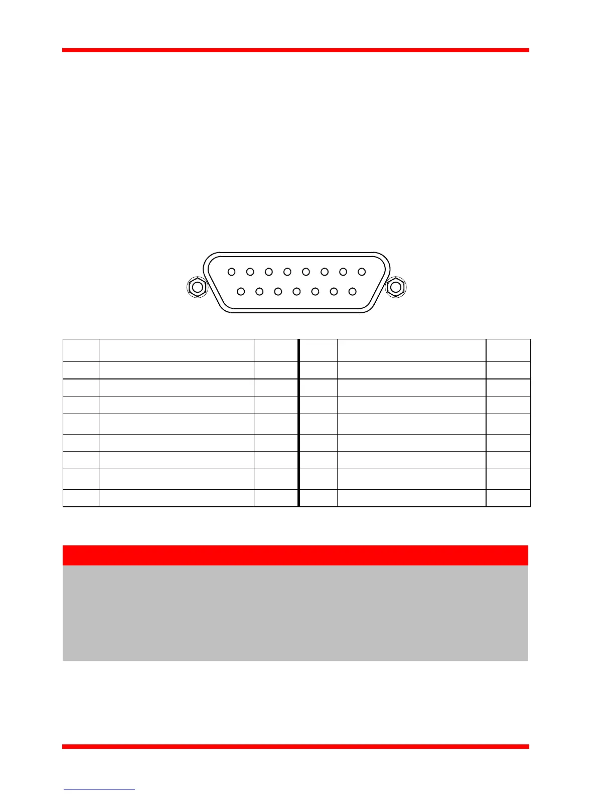
A.1 Rear Panel CONTROL IO Connector
The ‘CONTROL I/O’ is a 15-Pin D-Type, Female connector that exposes a number of
electrical signals useful for external control. It is possible to configure a particular
controller to respond to trigger inputs, generate trigger outputs or both respond to and
generate a trigger output - see Section 5.3.3. Motor jogging lines can be used to jog
the motor in bo th forward and reve rse directions from a remote han dset (Jogging
parameters (e.g. jog distance) are set via the GUI panel - see Section 5.3.1.).
The pin functions are detailed in Fig. A.1.
Fig. A.1 MOTOR I/O connector pin identification
Pin Description Return Pin Description Return
1 User 5V I/O 9 9 User 0V –
2 * Jog forwards 9 10 * Jog backwards 9
3 Not Used 9 11 ** Analog In 9
4
Tigger In
†
– 12 Trigger Out 9
5 User 0V – 13 Not Used –
6 RS232 TX – 14 RS232 RX 6
7
Digital (User) In
†
– 15 Digital (User) Out 9
8Keyed Pin –
Notes
* Jog inputs must be short circuit to User 0V (pin 9) in order to function.
** Analog In is 0 to 5V wrt 0V (pin 9). The input can be read by calling the
LLGetADCInputs method in the APT software - see the APTServer helpfile for
more details.
† The OFF voltage range is 0 to 0.4V, the ON voltage range is 4.5 to 5V.
Voltage greater than 5.5V will damage the input.