25
Two-, and Three-Channel Stepper Motor Controller
4.7 Graphical Control Of Motor Positions (Point and Move)
The GUI panel display can be changed to a graphical display, showing the position of
the motor channel(s). Moves to absolute positions can then be initiated by positioning
the mouse within the display and clicking.
To change the panel view to graph ical view, right click in the screen and select
‘Graphical View’.
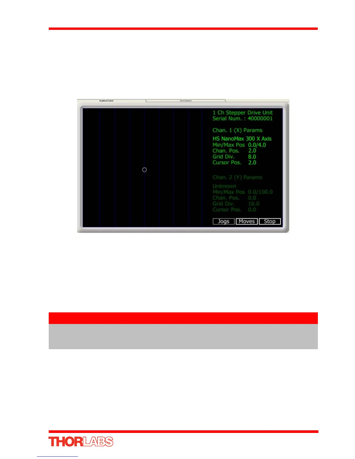
Fig. 4.6 Motor GUI Panel - Graphical View
Consider the display shown above for a Stepper Motor Drive Card fitted to a BSC203
APT stepper controller unit.
The right hand display shows the channel and motor unit parameters; i.e. controller
unit type and se rial number, associated stage and actuator type, min imum and
maximum positions, current position, units per grid division and cursor position. All
units are displayed in real world units, either millimetres or degrees.
The left h and display shows a circle , which represents the current position of the
motor associated with the specified controller (absolute position data is displayed in
the 'Chan Pos' field).
The vertical divisions relate to the travel of the stage/actuator associated with the
controller (the stage/actuator is selected in the ‘APT Config’ utility). For example, the
screen shot above shows the parameters for a 4 mm travel NanoMax 3-axis stage.
The graph shows 8 divisions in the X axis, whi ch relates to 0.5 mm of travel per
division (4.0 mm in total).
Note
The channel functionality of the BSC203 motor controller is accessed via
a single channel GUI panel, one panel for each motor drive card fitted.
The Channel 2 parameters are greyed out.