14 HA0365T Rev D Jan 2017
Chapter 3
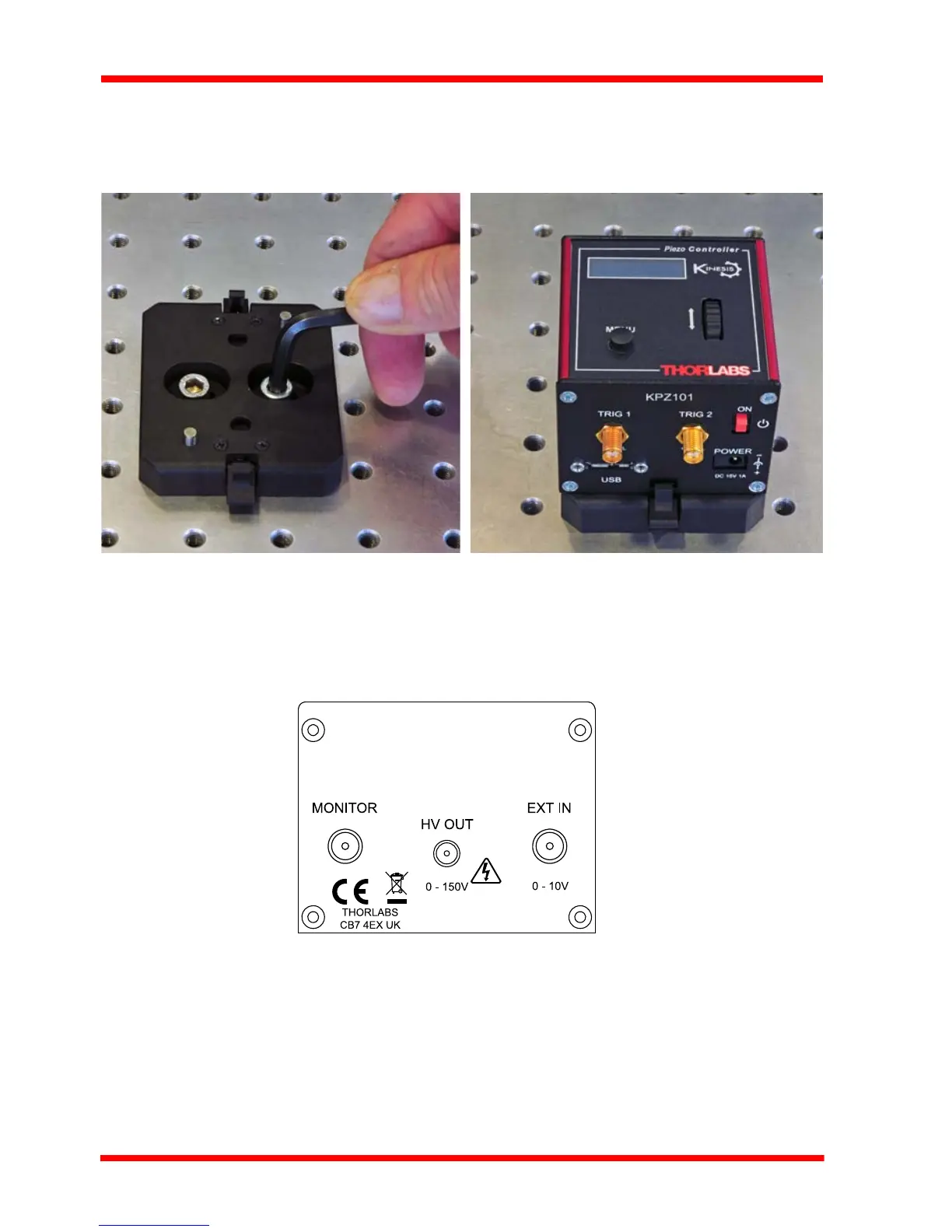
3.2.3 Using the Baseplate
The baseplate must be bolted to the worksurface before the K-Cube is fitted, as
shown below. The K-cube is then located on two dowels in the baseplate and secured
by two clips.
Fig. 3.1 Using The Baseplate
3.3 Electrical Installation
3.3.1 Rear Panel
Fig. 3.2 Rear Panel Connections
HV OUT (SMC connector) – 0 to 150V, 0 to 7.5mA. Provides the drive signal to the
piezo actuator. The maximum voltage (75V, 100V or 150V) is set via the top panel
(see Section 4.4.3.) or via the APTsoftware ‘Settings’ panel (see Section 6.2.).
EXT IN (SMA connector) – Used to conn ect an external analogue signal source to
control the operation of the cube. The input voltage range is 0 to +10V and the input
impedance is 12 kΩ.