EasyManua.ls Logo

THORLABS K-Cube Piezo Controller User Manual

THORLABS K-Cube Piezo Controller
78 pages
To Next Page IconTo Next Page
To Previous Page IconTo Previous Page
Page #5 background image
5
Chapter 2 Overview and Setup
2.1 Introduction
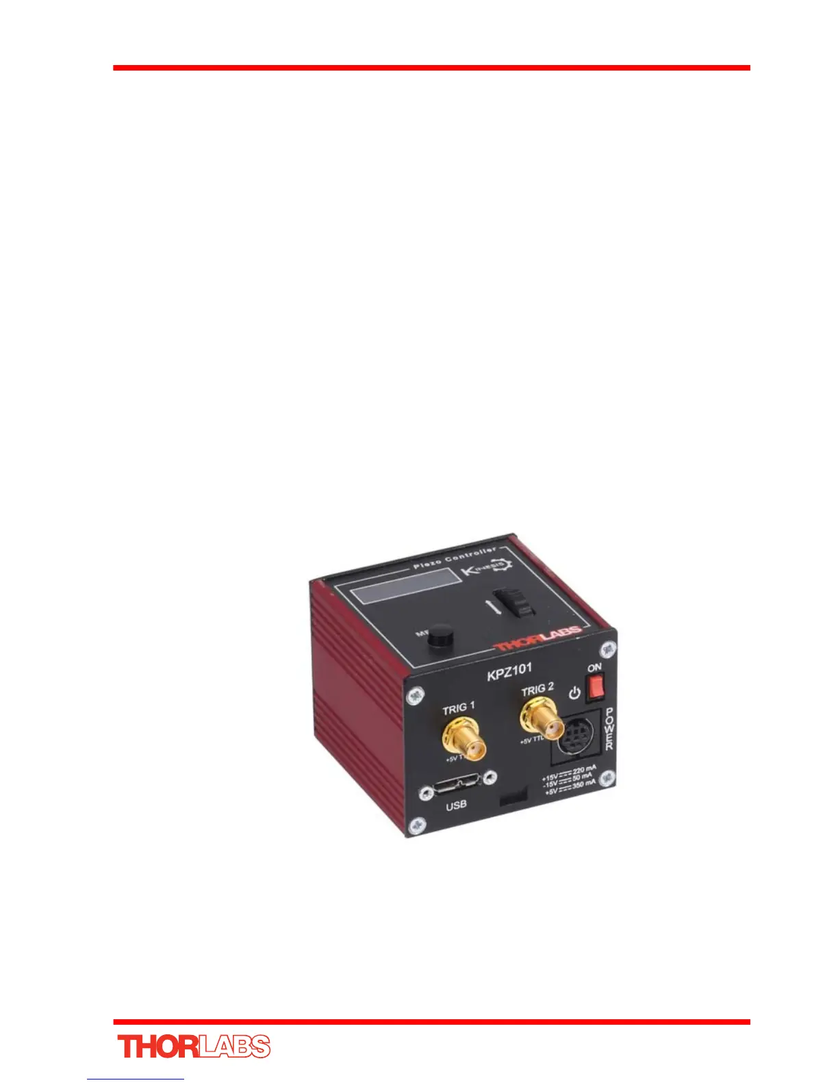
The K-Cube Piezo Co ntroller (KPZ101) is a ne w very compact sing le channel
controller/driver for easy man ual and automatic control of a wi de range of piezo
stacks and actuators. This driver is capable of delivering up to 150V of drive voltage
at 7.5mA - all owing operating bandwidths up to 1kHz (see specs). The KPZ101
provides immediate 'out of the box' operation with the Thorlabs complete range of
bare piezo stacks, piezo equipped actuators and piezo driven mirror mounts.
Furthermore, when operated together with the K-Cube Strain Gauge Reader unit
(KSG101), high precision closed loop operation is possible using the complete range
of feedback equipped piezo actuators available from Thorlabs.
For convenience the footprint of this unit has been kept to a minimum, measuring only
60mm x 60mm x 47mm (2.36” x 2.36” x 1.85”) and with the facility to directly mount
to the optical table close to the device under control. Table top operation also allows
minimal drive cable lengths for easier cable management. All manual controls a re
located on the top face of the unit – very convenient when manually adjusting piezo
positions using the digitally encoded adjustment pot and easy to read voltage display
(with brightness adjustment).
Fig. 2.1 K-Cube Piezo Driver (KPZ101)
Although compact in footprint, this unit offers a fully featured piezo control capability.
To support a wide variety of piezo devices the output range can be user selected to
75V, 100V or 150V. The resolution of the digitally encoded adjustment pot is easily
altered to provide very accurate p ositioning control. Direct hardware control of the
high voltage output can be facilitated using the low voltage input connector.
Question and Answer IconNeed help?

Do you have a question about the THORLABS K-Cube Piezo Controller and is the answer not in the manual?

THORLABS K-Cube Piezo Controller Specifications

General IconGeneral
ModelK-Cube Piezo Controller
TypePiezo Controller
Channels1
Max Output Current20 mA
Control InterfaceUSB, RS-232
Output Voltage0 - 75 V
Compatible Piezo ActuatorsThorlabs PZT Actuators
Weight0.1 kg

Summary

Chapter 1 Safety

1.1 Safety Information

General safety warnings and symbols used in the manual and on the product.

1.2 General Warnings

Specific warnings regarding high voltage, moisture, and proper insulation.

Chapter 2 Overview and Setup

2.1 Introduction

Introduces the KPZ101 as a compact, single-channel piezo controller/driver for various applications.

2.2 Power Options

Discusses available power supplies and controller hubs for the KPZ101.

2.3 APT PC Software Overview

Overview of the APT software suite, including GUI panels and programming libraries.

2.3.1 Introduction

Details the benefits of APT software for controlling multiple units and automating operations.

2.3.2 APTUser Utility

Explains the APTUser application for user interaction and control of APT hardware.

2.3.3 APT Config Utility

Describes the APTConfig utility for system-wide settings and configuration.

2.3.4 APT Server (ActiveX Controls)

Explains ActiveX Controls for direct hardware control and status reflection.

2.3.5 Software Upgrades

Mentions Thorlabs' policy on continuous product development and software upgrades.

Chapter 3 Getting Started

3.1 Install The Software.

Instructions for installing the APT software on a PC.

3.2 Mechanical Installation

Covers environmental conditions and mounting options for the unit.

3.2.1 Environmental Conditions

Specifies operating limits for temperature, humidity, and altitude.

3.2.2 Mounting Options

Details how to mount the unit using a baseplate or controller hub.

3.3 Electrical Installation

Details the rear panel connections for monitoring, HV output, and external input.

3.3.1 Rear Panel

Describes the HV OUT and EXT IN connectors and their functions.

3.3.2 Supply Voltage and Current Requirements

Lists the required supply voltages and current for the unit.

3.3.3 Front Panel

Explains the front panel connectors and controls, including POWER, USB, ON, and TRIG ports.

3.3.4 Connecting to a Power Supply

Step-by-step guide for connecting the unit to a DC power supply.

3.3.5 Powering Down The Unit

Safe procedures for powering down the unit, including saving parameters.

3.4 Connect The Hardware

Comprehensive steps for connecting the controller, actuator, and power supply.

3.5 Verifying Software Operation

Steps to run the APTUser utility and verify the GUI panel is active.

Chapter 4 Standalone Operation

4.1 Introduction

Introduces standalone operation and front panel controls for piezo moves.

4.2 Control Panel

Describes the physical controls and indicators on the unit's front panel.

4.2.1 Digital Display - Operating Mode

Explains the information shown on the digital display during operation.

4.3 Velocity Wheel Operation

Details how the velocity wheel is used for different move types and modes.

4.3.1 Voltage Adjust Mode

How to use the wheel to adjust drive voltage in Voltage Adjust Mode.

4.3.2 Go to Voltage

Using the wheel to set preset voltage values.

4.3.3 Jog to voltages

Configuring the wheel to 'jog' the drive voltage.

4.4 Settings Menu

Steps to access and navigate the unit's settings menu.

4.4.1 Menu Overview

A flowchart showing the structure and options within the settings menu.

4.4.2 Menu Option - HV output

How to enable or disable the drive output via the settings menu.

4.4.3 Menu Option - Voltage range

Setting the maximum drive voltage for the connected piezo actuator.

4.4.4 Menu Option - Feedback mode

Selecting between open and closed loop operation modes.

4.4.5 Menu Option - Analogue input

Configuring the analogue input source for different operational modes.

4.4.6 External Inputs

Describes the 3 external inputs and their function in open/closed loop modes.

4.4.7 Menu Option - Joystick mode

Setting the operating mode of the joystick wheel (e.g., Jog, Voltage Adjust, Go to Voltage).

4.4.8 Menu Option - Joystick menu

Adjusting parameters like Step size and Speed based on Joystick mode.

4.4.9 Menu Option - Teach voltage

Setting preset voltages (V1, V2) for 'Go to Voltage' mode.

4.4.10 Menu Option - 8 Wheel lock

Disabling the wheel to prevent accidental motion.

4.4.11 Menu Option - Brightness

Adjusting the brightness of the LED display.

4.4.12 Menu Option - Disp.Timeout

Setting the display timeout period to prevent burn-in.

Chapter 5 Operation - Tutorial

5.1 Introduction

Guides the user through typical actions and parameter adjustments using APT software.

5.2 Using the APT User Utility

Explains how to use the APTUser.exe application for interacting with APT hardware.

5.3 Introduction to Open and Closed Loop Operation

Explains the two distinct modes of operation: open loop and closed loop.

5.3.1 Description of Open Loop Mode

Shows a block diagram of the piezo controller in open loop mode.

5.3.2 Description of Closed Loop Mode

Shows a block diagram of the piezo controller in closed loop mode.

5.4 Open Loop Operation

Details how to connect power and actuator for open loop operation.

5.4.1 Connecting The Actuator and Power

Steps to connect power supply and piezo actuator for open loop use.

5.4.2 Entering the piezo voltage

How to enter a specific voltage value via the digital display.

5.4.3 Moving the Piezo using the ‘Output' control

Using the front panel 'Output' knob to adjust voltage.

5.4.4 Jogging the Piezos

Using jog buttons to move the piezo based on step size settings.

5.4.5 Using the Controller as a Piezo Amplifier

Configuring the unit to use an external 0-10V signal source.

5.5 Operation with Other members of the K-Cube Family

How KPZ101 can be extended with KSG101 and TNA001.

5.5.1 Introduction

Introduces integration with other K-Cube family members like KSG101 and TNA001.

5.6 Closed Loop Operation

Explains basic operation with a Strain Gauge Reader K-Cube.

5.6.1 Electrical Connections and Software Settings - Hub Operation

Setup procedure for using KPZ101 and KSG101 on a KCHx01 hub.

5.6.2 Revision 2 Piezo Driver Hub Mounting Options.

Discusses various bay mounting options and associated settings for controller hubs.

5.6.3 Electrical Connections and Software Settings - Off Hub (Hard Wired) Operation

Describes setup for controlling a piezo stage without a controller hub.

5.6.4 Setting the Position Sensor Zero

Procedure to zero the position sensor for actuators with feedback.

5.8 Load Response

Shows the KPZ101's response to varying loads and frequencies.

5.9 Creating a Simulated Configuration Using APT Config

Steps to create simulated hardware configurations for offline software development.

Chapter 6 Software Reference

6.1 GUI Panel

Shows the graphical user interface displayed when accessing the controller via APTUser.

6.2 Settings Panel

Explains the settings window for configuring parameters like jog step size and input sources.

6.2.1 Settings tab

Details the 'Settings' tab within the Piezo Driver Settings window.

6.2.2 Panel/Triggering tab

Describes the 'Panel/Triggering' tab for adjusting wheel, trigger, and display settings.

Wheel Direction

Specifies how wheel rotation direction affects voltage change.

Triggering Introduction

Introduces the bidirectional trigger ports and their configuration.

Trigger Settings

Details trigger modes like Disabled, Digital Input, Trig In Jog Up/Down.

Disp. Brightness

Adjusts the brightness of the LED display and timeout settings.

Persist Settings to Hardware

Allows saving parameters to the unit for automatic loading on power-up.

Appendix A Connector Pinout Details

A.1 Power Connector

Details the pin identification for the mini-DIN power connector.

A.1.1 Pin Identification

Shows the pin numbering and description for the POWER connector.

Appendix B Preventive Maintenance

B.1 Cleaning

Provides instructions and warnings for cleaning the unit's fascia.

Appendix C Specifications and Associated Products

C.1 Specifications

Lists the technical specifications of the KPZ101 Piezo Controller.

C.2 Associated Products

Lists related Thorlabs products like cables, hubs, and accessories.

Appendix D Piezo Control Method Summary

Methods

Summarizes the methods available in the Piezo ActiveX Control for hardware interaction.

Properties

Lists properties of the Piezo ActiveX Control for hardware association and help access.

Appendix E Piezo Operation - Background

E.1 The Piezoelectric Effect

Explains the basic principle of piezoelectricity and actuator construction.

E.2 Hysteresis

Describes hysteresis as an inherent problem in piezoelectric actuators.

E.3 Position Sensing and Feedback Control

Explains how position sensing and feedback loops eliminate hysteresis.

Appendix F Regulatory

F.1 Declarations Of Conformity

States compliance with FCC rules and European directives.

F.1.1 For Customers in Europe

Refers to Section F.3 for European compliance details.

F.1.2 For Customers In The USA

Details FCC compliance for Class A digital devices.

F.2 Waste Electrical and Electronic Equipment (WEEE) Directive

Explains compliance with the WEEE directive for product return.

F.3 CE Certificate

Presents the EU Declaration of Conformity and CE marking details.

Appendix G Thorlabs Worldwide Contacts

USA, Canada, and South America

Provides contact information for Thorlabs in North America.

Europe

Provides contact information for Thorlabs in Europe.

UK and Ireland

Provides contact information for Thorlabs in the UK and Ireland.

Scandinavia

Provides contact information for Thorlabs in Scandinavia.

France

Provides contact information for Thorlabs in France.

Brazil

Provides contact information for Thorlabs in Brazil.

Japan

Provides contact information for Thorlabs in Japan.

China

Provides contact information for Thorlabs in China.

Related product manuals