62 HA0365T Rev D Jan 2017
Chapter 6
Wheel Direction
The direction of a voltage change initiated by the velocity wheel is specified as follows:
Direction Sense Positive - Up wards rotation of the wheel results in a positive
change (i.e. increased voltage).
Direction Sense Negative - Upwards rotation of the wheel results in a negative
change (i.e. decreased voltage).
Triggering Introduction
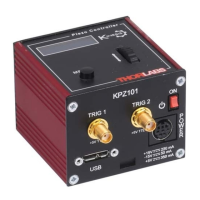
The K-Cube piezo controller has two bidirectional trigger ports (TRIG1 and TRIG2)
that can be used to read an external logic signal or output a logic level to control
external equipment. Either of them can be independently configured as an input or an
output and the active logic state can be selected High or Low to suit the requirements
of the application. Electrically the ports output 5 Volt logic signals and are designed
to be driven from a 5 Volt logic.
When the port is used in the input mode, the logic levels are TTL compatible, i.e. a voltage level
less than 0.8 Volt w ill be recognised as a logic LOW and a level greater
than 2.4 Volt as a
logic HIGH. The input contains a weak pull-up, so the state of t he input with nothing
connected will default to a logic HIGH. The weak pull-up feature allows a passive device,
such as a mechanical switch to be connected directly to the input.
When the port is used as an out put it provides a push-pull drive of 5 Volts, with the maximum
current limited to approximately 8 mA. The current limit prevents damage when the output is
accidentally shorted to ground or driven to the opposite logic state by external circuity.
Warning: do not drive the TRIG ports from any voltage source that can produce an
output in excess of the normal 0 to 5 Volt logic level range. In any case the voltage at
the TRIG ports must be limited to -0.25 to +5.25 Volts.
Trigger Settings
When configured as an input, the TRIG ports can be used as a general purpose digital
input, or for triggering a relative, absolute or home move. When used for triggering a
move, the port is edge sensitive. In other words, it has to see a transitio n from the
inactive to the active logic state (Low->High or High->Low) for the trigger input to be
recognized. For the sa me reason a sustained logic level will not trigg er repeated
moves. The trigger input has to return to its inactive state first in order to start the next
trigger. The mode is set in the Trig 1 Mode and Trig 2 Mode parameters as follows:
Disabled - The trigger IO is disabled
Digital Input - General purpose logic input (read through status bits using the
LLGetStatusBits method).
Trig In Jog Up - Only applicable in Open Loop mode. Input trigger for voltage
step up. On receipt of the trigger, the drive voltage increases by the value set in
the Wheel Step Size parameter.

 Loading...