64
Appendix A Connector Pinout Details
A.1 Power Connector
A.1.1 Pin Identification
Thorlabs recommends that the piezo cube is operated with Thorlabs power supply
TPS002, as it was specifically designed for use with this product. However, to enable
customers to use the cube in in stallations where a ±15V and 5V power is already
available, the piezo cube can be operated with a different external power supply, such
as a bench or lab supply.
In this case however, extreme care must be taken to ensu re that it meets th e
specifications and connected to the cube correctly. Out of tolerance supply voltages
or incorrect connection, applied even momentarily, can result in the sen sitive
electronic inside the cube getting damaged, invalidating warranty.
The cube uses a standard “mini-DIN” type of input connector, the corresponding plug
is available from most standard electronics suppliers.
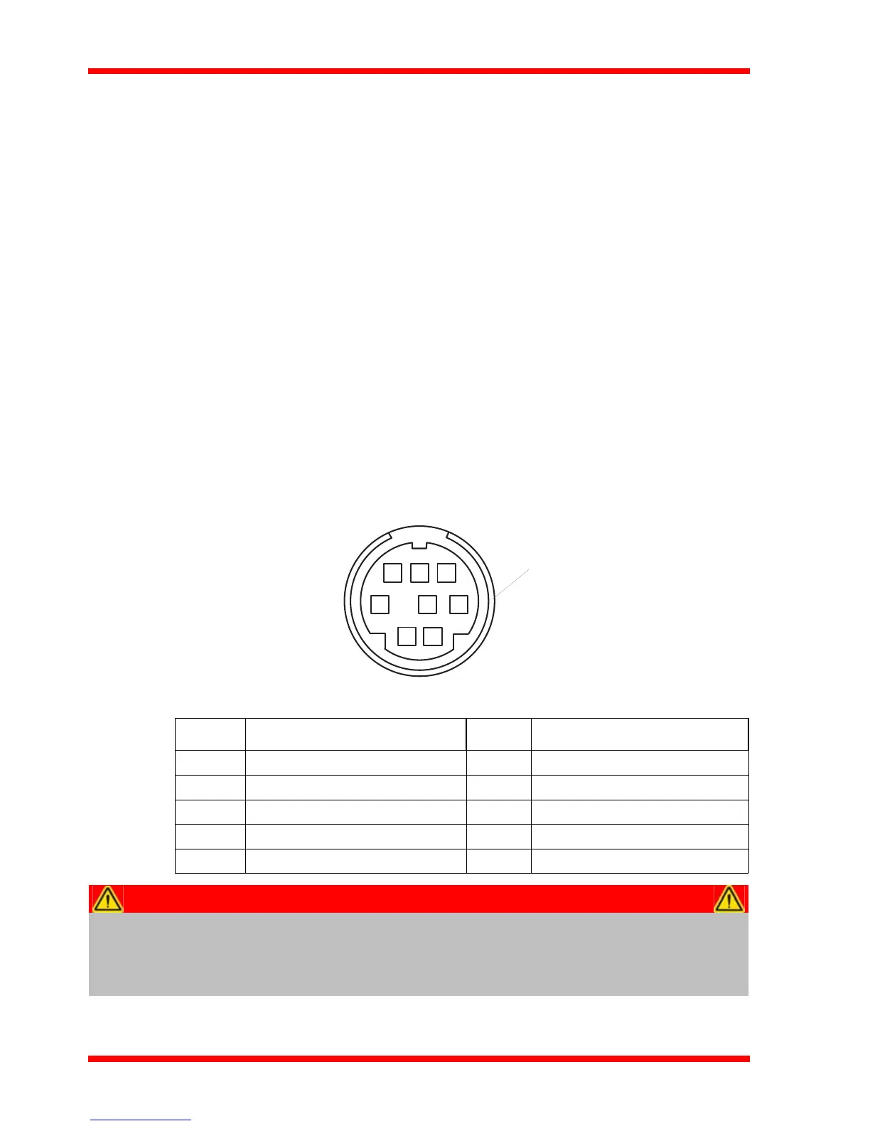
Fig. A.1 shows the mini-DIN socket as vi ewed by l ooking at the rear panel of the
cube. The pin numbering follows the standard for mini-DIN connectors.
Fig. A.1 POWER Connector Pin Identification
Pin Description Pin Description
1 +5V 6 Common Ground
2 +5V 7 Common Ground
3 -15V 8 Common Ground
4 +15V Shield Common Ground
5+5V
Warning
When wiring the mini-DIN plug, ensure that all the ground pins are used and
the shield is connected to common ground. This provides a level of protection
against overvoltages due to loss of ground. A “loss of ground” condition can
seriously damage the electronics inside the cube.