39
K-Cube Piezo Driver
In closed loop, the role of the external inputs changes, and the selected input receives
the position signal from the external position reader. The DSP now implements a
digital PI (proportional-integral) control feedback loop. This control loop monitors the
actual position reading and adjusts the high voltage output to maintain a constant
position (set point). This set point can be varied by adjsuting the OUTPUT pot on the
front panel or the Output control on the GUI.
5.4 Open Loop Operation
5.4.1 Connecting The Actuator and Power
1) Connect the power supply as detailed in Section 3.3.4.
2) Connect the Piezo Actuator to the HV OUT terminal on the rear panel.
The following procedures explain how the piezo actuator is driven. In open loop mode,
the piezo can be positioned in three ways: by entering a voltage, by using the ‘Output’
potentiometer or by clicking the ‘Jog’ buttons.
5.4.2 Entering the piezo voltage
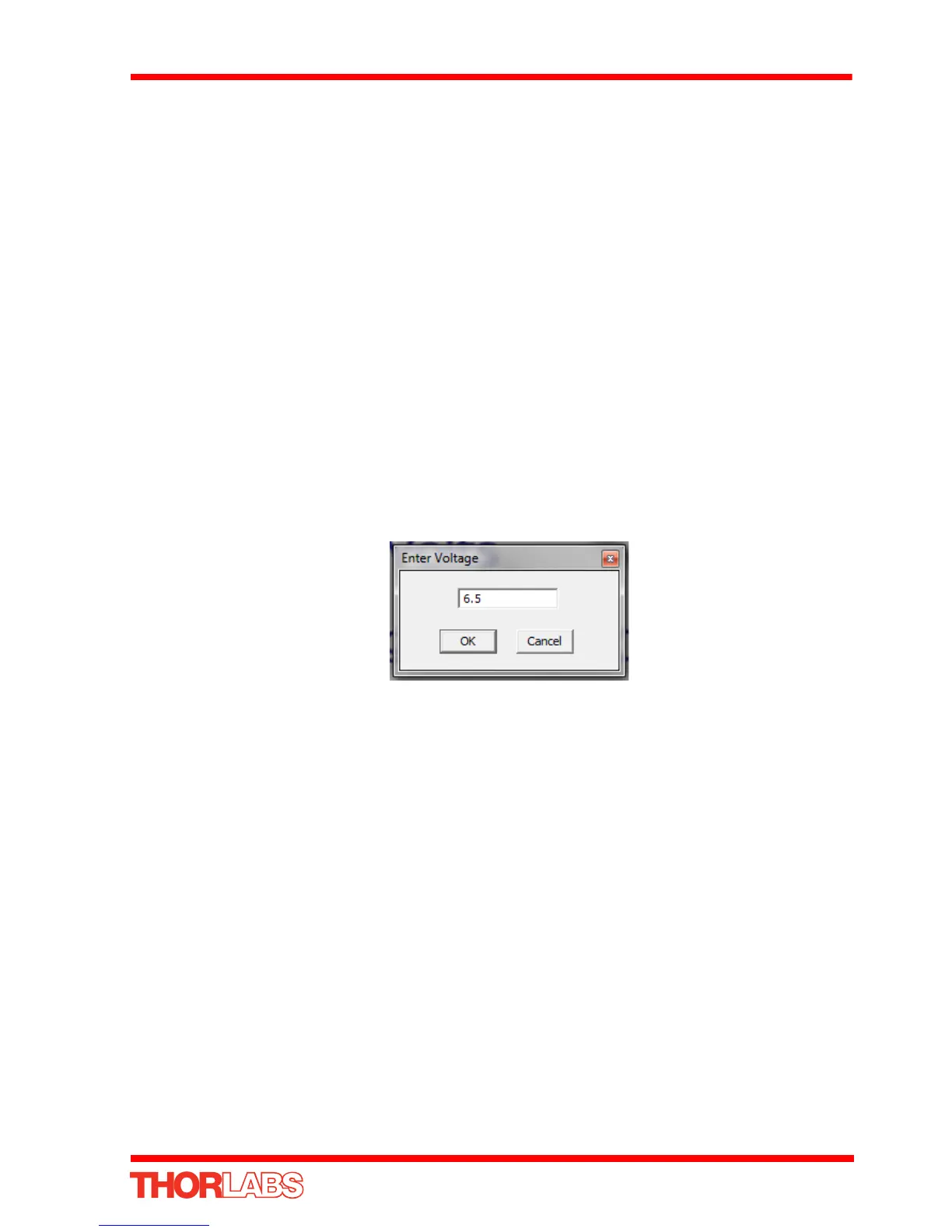
1) Click the digital display..
Fig. 5.5 Voltage Popup Window
2) Enter a voltage into the pop up window (6.5 in our example above)
3) Click ‘OK’. Notice that the display counts up to 6.5 to indicate an applied voltage
of 6.5V.