38 HA0365T Rev D Jan 2017
Chapter 5
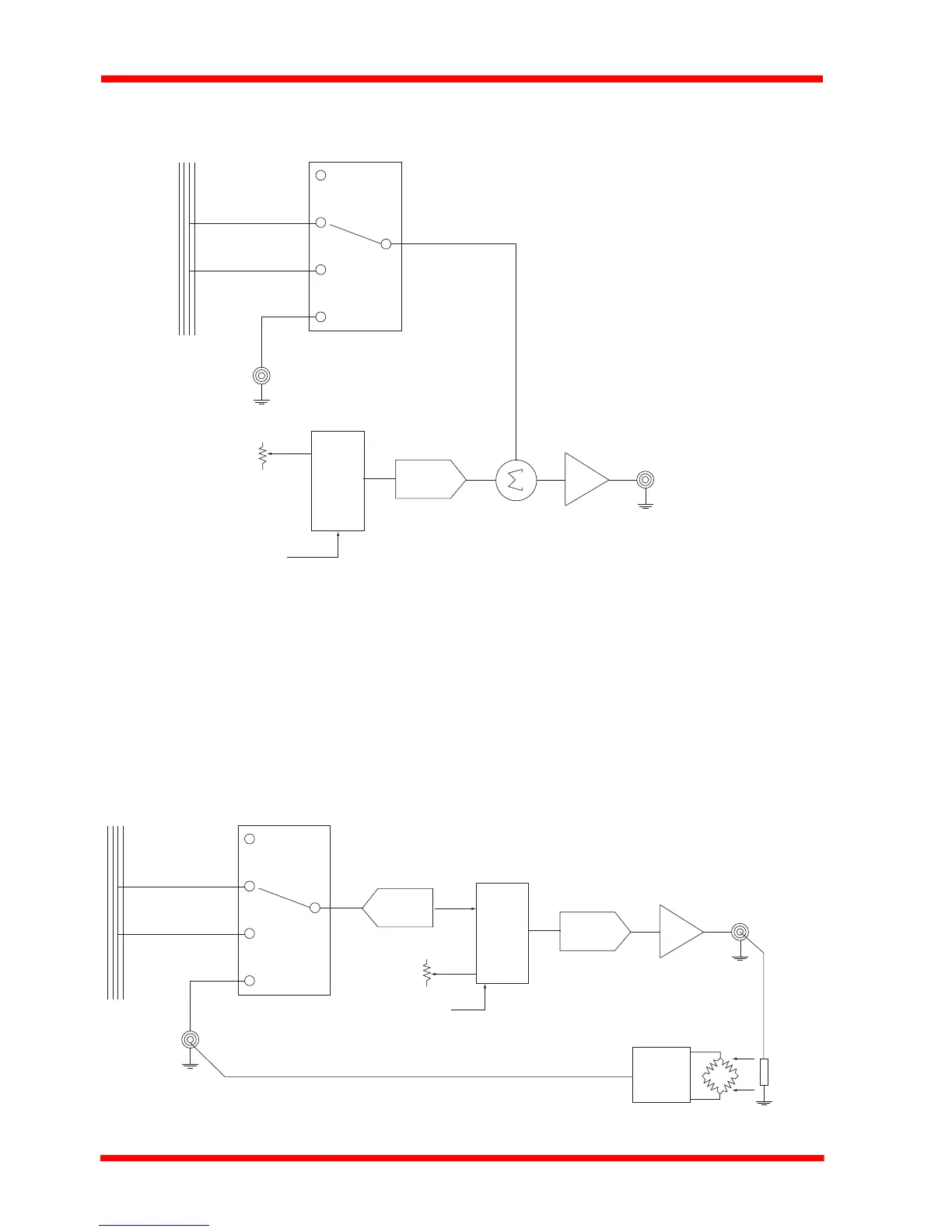
5.3.1 Description of Open Loop Mode
Fig. 5.3 shows a simplified block diagram of the piezo controller in open loop mode.
Fig. 5.3 Open Loop Schematic Diagram
The output voltage is controlled by the DSP, allowing the APT server to set the output
voltage. The output voltage can also be controlled by the top panel potentiometer. In
addition, one o f the 3 p ossible external inputs (SMA in put, Hub Channel 1 or Hub
Channel 2) can also be added to the signal that controls the output voltage.
5.3.2 Description of Closed Loop Mode
Fig. 5.4 shows a simplified block diagram of the piezo controller in closed loop mode
(with the rear panel EXT IN terminal used for feedback)..
Fig. 5.4 Closed Loop Schematic Diagram
Off
Hub Channel 1
Hub Channel 2
EXT SMA
DSP
Pot
USB
DAC HV
SMB
Hub
Off
Hub Channel 1
Hub Channel 2
EXT SMA
DSP
Pot
USB
DAC
ADC
HV
SMC
HV OUT
Closed Loop
TSG001
Piezo
actuator
position signal
Hub