49
K-Cube Piezo Driver
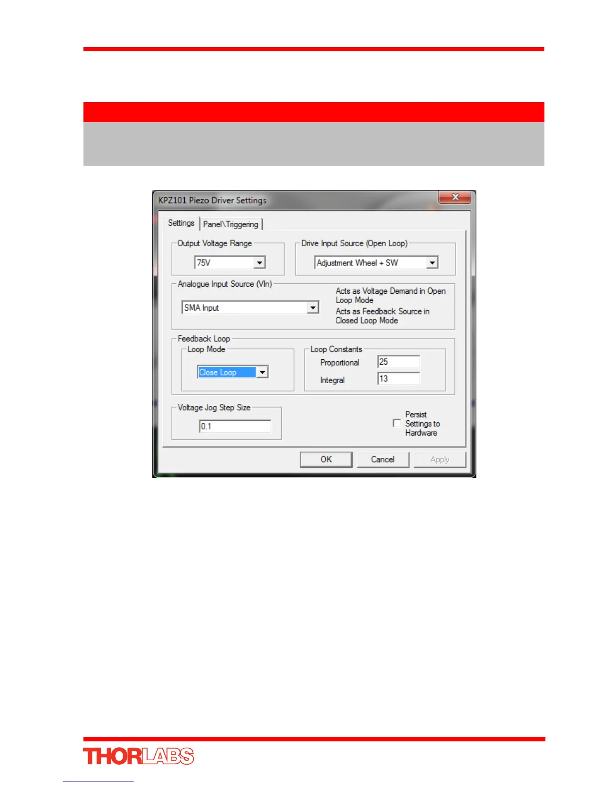
10) Click the ‘Settings’ button on the GUI pan el of the Pi ezo Driver to d isplay the
Settings panel (shown below).
Fig. 5.14 Piezo Driver Settings
11) Make the following parameter settings, as shown in Fig. 5.14
Output Voltage Range - Set the corresponding voltage for the piezo being
driven, 75V, 100V or 150V.
Drive Input Source (Open Loop) - Select Adjustment Wheel + SW
Analogue Input Source (EXT IN) - Select SMA Input
Feedback Loop Mode - Select Closed Loop
12) If desired, click the ‘Persist Settings To Hardware’ box. These settings will then be
loaded on each power up cycle
13) Click ‘OK to save the settings.
14) Refer to Section 5.6.4. for instructions on setting the position sensor zero value.
Note
To identify the piezo unit associated with the GUI panel, click the ‘Ident’
button; the Power LED on the panel of the asssociated controller flashes
for a short period.