WARNER ELECTRIC EUROPE - Rue Champfleur, B.P. 20095, F - 49182 St Barthélemy d’Anjou Cedex SM421gb - rev 12/09 4/5
• Engage the disc
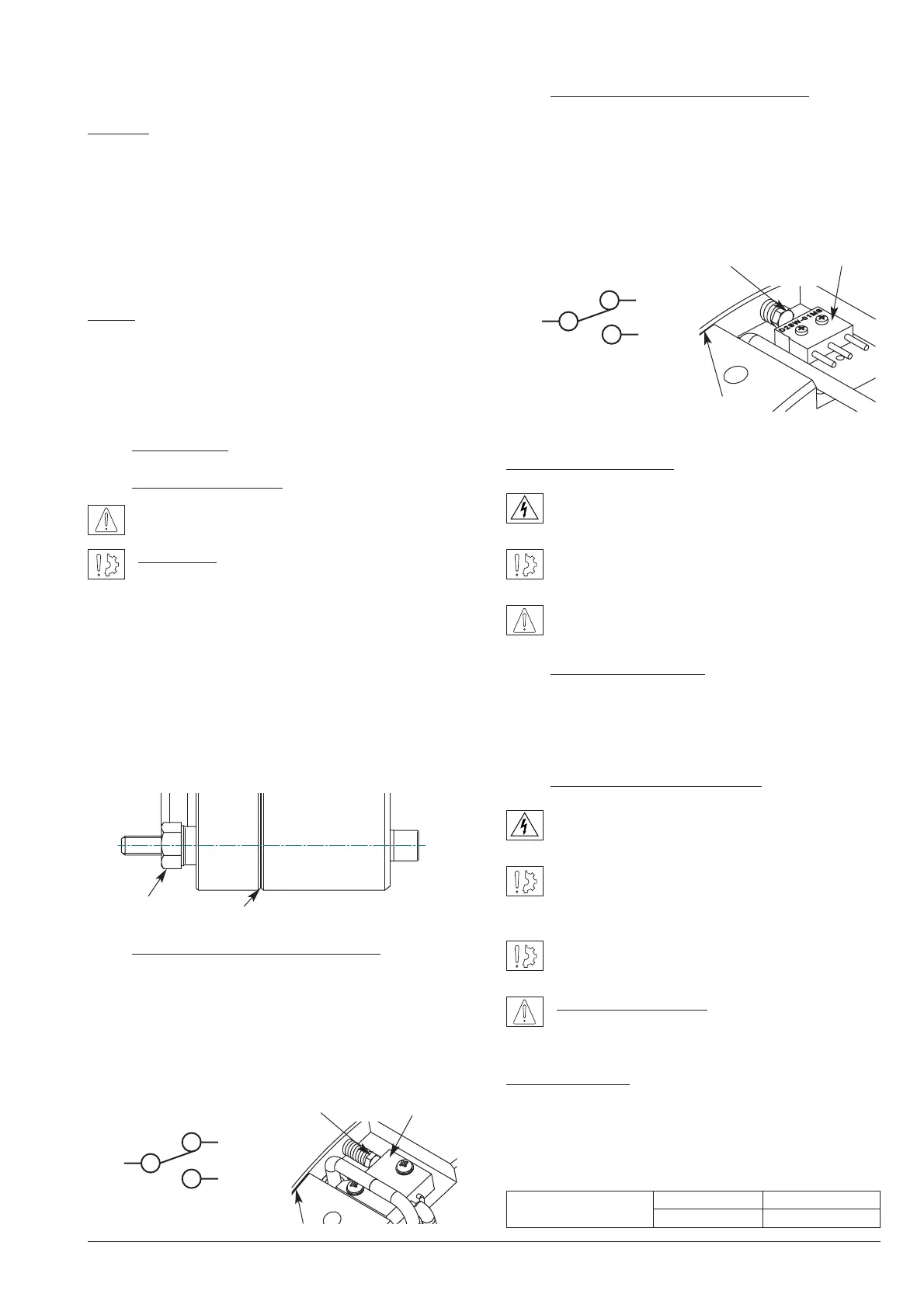
Caution: When installing and should the brake ever be dis-
mantled, make sure that the friction disc boss is the right
way round when the brake is re-assembled (see Fig.1).
• Engage the brake (line up the brake on the fixing thread)
• Tighten the 4 fixing screws CHc M10 (star sequence
tightening, Cs: 25 Nm). Finish tightening with a torque,
44 Nm (±10%)
NOTE: Secure the fixing screws (use a safety washer or
thermoplastic liquid such as Loctite)
• Remove the 2 transport screws
• Make all the electrical connections
4 Maintenance
4.1 Adjusting the airgap
Check the airgap at each maintenance inspection.
Reminder: This brake is intended for a static appli-
cation as a safety brake. Any dynamic braking is
restricted to emergency and test braking. Normal use will
not lead to any noticeable wear on the lining. If for any rea-
son it should be necessary to adjust the airgap, proceed
as follows:
Loosen the attachment screws slightly. Adjust airgap with
adjusting screws (hexagonal bar 21/flat) until they slightly
exceed the nominal value (see Table 1). Tighten the screws
(refer to point 3.3 Installation). Carry out a few successive
draws and releases. Check the value of the airgap at sev-
eral points. Repeat the whole process if necessary.
4.2 Adjusting the microswitch MP320
Slide a wedge 0,15 mm thick close to the screw between
the face of the magnet and the moving armature. Switch
on the current and tighten the adjusting screw H M4 (7/flat)
in contact with the microswitch until you reach the com-
mutation point. Remove the wedge. Check that it functions
correctly by a few successive draws and releases (see
Fig. 4a).
4.3 Adjusting the microswitch OMRON
Slide a wedge 0,10 mm thick close to the screw between
the face of the magnet and the moving armature. Switch
on the current and tighten the adjusting screw H M4 (7/flat)
in contact with the microswitch until you reach the com-
mutation point. Remove the wedge. Check that it functions
correctly by a few successive draws and releases (see
Fig. 4b).
Operation microswitch
Current range 10 mA min. to 100 mA max. at 24
VDC
Maximum electrical lifetime of the microswitch
ensure only by switching under resistive load.
When the coil is switched off, the microswitch is in
the " NC " position.
5 Electrical connection
Brake ERS VAR08 SZ 1050/---- operates on a direct
current supply. Polarity does not affect the way the brake
operates.
5.1 Important recommendations
All works on the electrical connections have to be
made with power off.
Make sure that the nominal supply voltage is always
maintained (a lack of power results in a reduced
maximum airgap).
When switching on DC-side the coil must be
protected against voltage spikes.
Emergency braking : for emergency braking the
switching OFF must be connected on DC side, in
order to obtain short engaging time of the brake.
Service braking : for service braking, the switching OFF
and the switching ON must be connected on AC current
side, in order to obtain silent switching.
The connecting wires must be thick enough to help prevent
sudden drops in voltage between the source and the brake