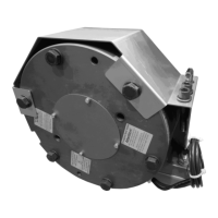
2Precautions and restrictions on use
2.1 Restrictions on use
For the brake to comply with directive 95 / 16 / EC,
the integrator must observe the general conditions
for installations and use as defined in the EC type certifi-
cate ref. ABV 592/1 of 12th Feb. 2003 drawn up by the
TÜV Munich, including the mandatory use of a speed lim-
iting device, in compliance with EN 81-1 paragraphs 9.9
and 9.10.10.
This brake is designed to work in dry conditions.
Friction faces must be kept completely clean of
any oil, grease or abrasive dust.
If maximum rotation speeds are exceeded, the guar-
antee is no longer valid.
This brake may only be used in a “horizontal axis”.
The customer must be careful not to alter the fac-
tory-set airgap, this is in order to ensure the brakes may be
properly released.
This brake is designed for a maximum ambient
temperature of 40°C (coating class 155°C). The
maximum temperature in continual use is 100°C.
This brake is designed for static applications. Any
dynamic braking is restricted to emergency brak-
ing and test braking. This brake can in no way replace the
safety braking system used during lift descent.
2.2 Precautions and safety measures
During maintenance, make sure that the mecha-
nism to be braked by the brake, is stopped and
that there is no risk of it accidentally starting up. All inter-
vention have to be made by qualified personnel, owning this
manual.
Any modification made to the brake without the
express authorisation of a representative of Warner
Electric, in the same way than any use out of the contrac-
tual specifications accepted by "Warner Electric", will result
in the warranty being invalidated and Warner Electric will
no longer be liable in any way with regard to conformity.
When switching on DC-side the coil must be pro-
tected against voltage peaks.
WARNER ELECTRIC EUROPE - Rue Champfleur, B.P. 11095, F - 49182 St Barthélemy d’Anjou Cedex SM344gb - rev 01/06 3/5
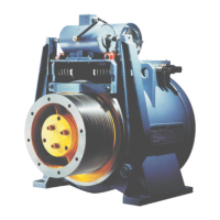
3 Installation
3.1 Transport / storage
This brake is delivered in standard packaging that will keep
it intact for a period of 6 months during ground, air or sea
transport towards neighbouring continents (without
crossing the tropics).
3.2 Handling
Avoid any impact to the brake so that its perform-
ance is not impaired.
When handling, use the threads for eye hooks
intended for this purpose.
Never lift the brake by its cables.
3.3 Installation
This brake is designed to work in dry conditions.
Friction faces must be kept completely clean of
any oil, grease or abrasive dust.
Specifications for the customer‘s friction
face :
Material: Steel (150 to 250 HV) or cast iron
Roughness ≤ Ra 3,2
Protection: Phosphatizing (dry) or nitriding
Geometric tolerances:
The brake is delivered pre-assembled with pre-set
microswitches and airgaps. The fixing screws, the hub and
the O-rings are supplied separately. The O-rings are not
pre-assembled on the hub.
• Retighten the 3 transport screws CHc M8
•Mount the hub on the customer’s shaft
• Mount the O ring on the hub (see Fig.1)
• Engage the rear disc on the hub