OPERATING MANUAL NBS MAINTENANCE
ThyssenKrupp Aufzugswerke GmbH
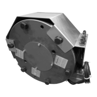
7. Repairs
7.1 Replacement of the NBS emergency brake
Note: if the brake is defective, the complete NBS emergency brake is to be
replaced in general.
Disconnect the power from the drive and secure it against unauthorised
activation. Disconnect the cable connections to the terminal box such as the
magnet connection, monitoring switch and thermal switch.
Screw the release screws into the brake housing.
Mark the location of the brake in relation to the housing; undo the securing
bolts of the brake. Do not pull out of the holes; remove the protective cover.
Screw the eye bolt into the threaded hole on the brake housing as a transport
aid. See Fig. 7.1.2.
Place the brake housing into the transport position by turning the
handwinding wheel.
Attach the eye bolt to lifting gear (crane or block and tackle) and pull off
carefully.
Pull the friction disk(s) and hub off the worm drive shaft.
Remove the preservative from the contact surfaces of the brake and clean.
Replace the O-rings on the toothed shaft end and hub with new ones and
grease lightly.
Push the hub onto the shaft end of the worm drive shaft.
Push the friction disk(s) onto the hub.
Attach the new brake housing with the eye bolt to the lifting gear.
Place the brake housing at the shaft end, align it and join it to the bearing
flange by turning in the opposite direction beyond the friction disk(s) and hub.
Align the location of the brake housing to the threaded hole by turning the
handwinding wheel and screw on loosely. Here, the switch and cable
connection should be arranged at the bottom left (arranged with direction of
view towards the brake in front of the drive). The screws must be seated on
detent edged washers (DIN 0833) to prevent inadvertent loosening.
Remove the brake release screws with screw head marked in red from the
brake housing.
Note: Nothing in the sealed setting of the manufacturer may be changed. If
the brake setting is not proper and adequate (air gap, contact space), it is to
be replaced with a new brake.
Fit the protective cover to the brake. Screw in the securing bolts of the brake
and use a torque wrench to tighten them alternately until the prescribed
torque is reached.
All connections, see chapter 3.6.
Switch on the drive; check the function and effect of the brake: switch on and
off at the control unit, observing the temporal sequence of the individual
switching sequences.
Run a brake test. Description in chapter 6.1