OPERATING MANUAL NBS TECHNOLOGY
ThyssenKrupp Aufzugswerke GmbH
3. Technical data
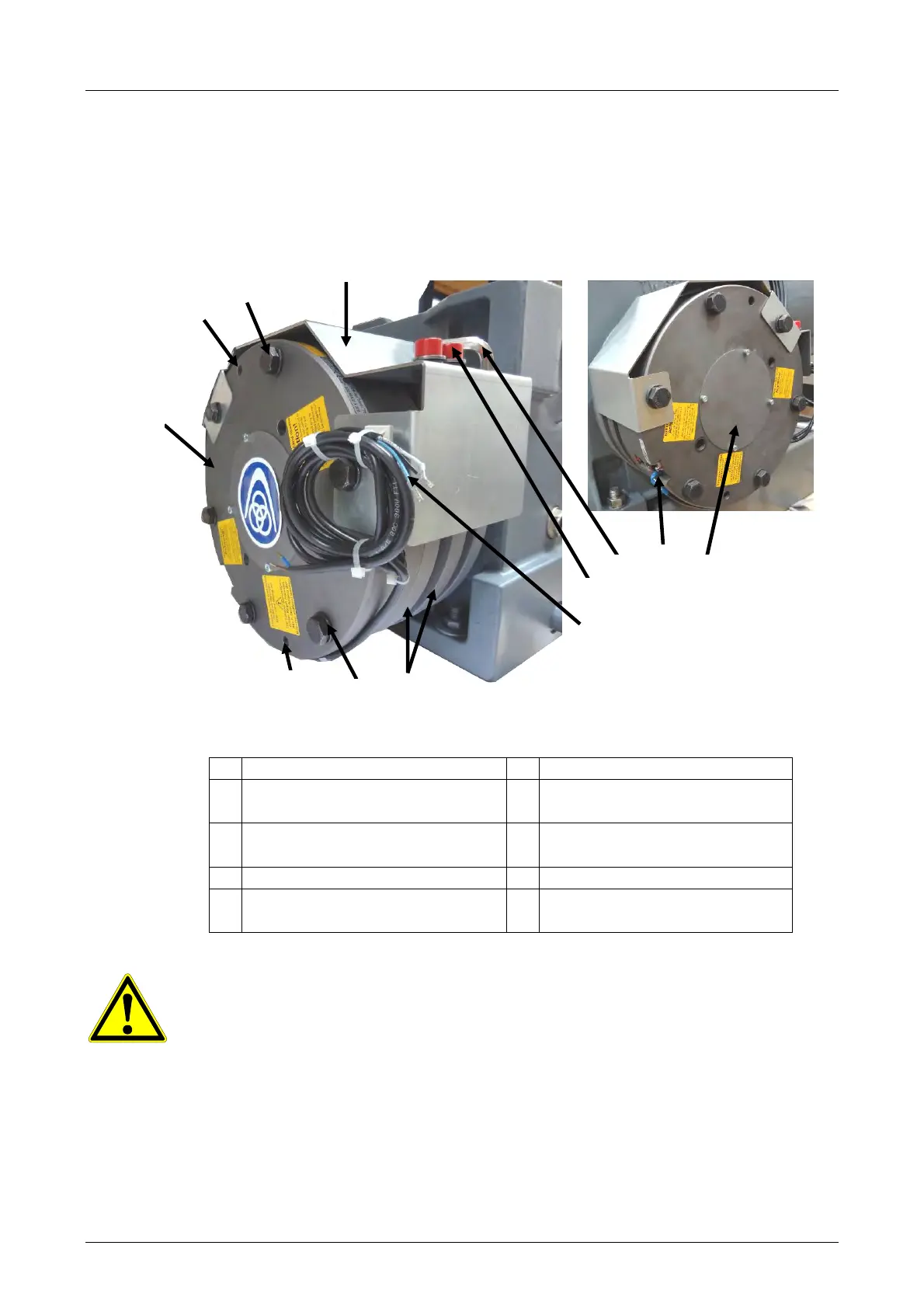
3.1 Mounting the NBS, TW45C
Fig. 3.1
1 Guard plate for brake 6 Brake test switch
2 Mounting bolts for brake to
gear
7 Screw for manual
emergency release
3 Thread for emergency release
8 Allen key for emergency
release
4 Brake (NBS) 9 Coil connection
5 Anchor disc / intermediate
disc
10
Sealing cap for shaft end
NB: The brake release screws marked in red, incl. washers, are to be
screwed into the threaded hole with the supplied Allen key. They may only be
fitted in the event of emergency measures (rescuing persons) or for
inspection / testing work.
Before commissioning the drive, they are to be removed from the brake
housing and reinserted together with the Allen key into the mounts in the
guard plate.
It is not possible to drive the motor with a manually opened emergency brake
or at switch position "Open" on the selector switch of the control unit.
1
9
7
8
6
10
5
2
3
3
2
4
Fig. 3.1.1