OPERATING MANUAL NBS ASSEMBLY
ThyssenKrupp Aufzugswerke GmbH
5. Assembly
5.1 Installation instructions
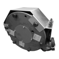
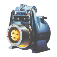
The NBS emergency brake is fitted to the drive, fully mounted and adjusted.
The setting at the plant must not be changed.
The control unit is intended to be fitted to the wall of the machine room. If
the rooms adjoining the machine room are living quarters / bedrooms, sound
insulation measures must be taken when mounting the unit. The mounting
dimensions and other dimensions can be found in chapter 2.4.
The terminal box for connection of the control unit is to be mounted as close
as possible to the NBS emergency brake on the site. (For example on the
frame or base of the drive.
The additional switch for triggering the emergency braking device is to be
mounted on the speed governor or the existing governor is to be replaced by
a governor with a fitted additional switch. Alternatively, a switch with a
second contact for a separate circuit of the NBS operation can be used.
See chapter 2.5
5.2 Terminal connecting information
Connections, see chapter 3.
The cable connections required for connection are delivered ready-made.
See specifications in the installation plan, chapter 3