WARNER ELECTRIC EUROPE - Rue Champfleur, B.P. 20095, F - 49182 St Barthélemy d’Anjou Cedex SM348gb - rev 01/06 4/5
• Tighten the 8 fixing screws CHc M12(Cs: 130 Nm
±10%) (star sequence tightening, to an initial torque of
50 Nm)
NOTE : Secure the fixing screws (use a safety washer or
thermoplastic liquid such as Loctite).
• Remove the 3 transport screws
• Make all the electrical connections
4 Maintenance
4.1 Adjusting the airgap
Check the airgap at each maintenance inspection.
Reminder: This brake is intended for a static appli-
cation as a safety brake. Any dynamic braking is res-
tricted to emergency and test braking. Normal use will not
lead to any noticeable wear on the lining. If, for any reason,
it should be necessary to adjust the airgap, proceed as fol-
lows:
• Loosen the fixing screws slightly
• Adjust the airgap (Fig. 3) using the adjusting screws
(hexagonal bar, 21/flat) until it slightly exceeds the
nominal value (see table 1)
• Tighten the screws (refer to point 3.3 Installation)
• Carry out a few successive draws and releases and
check the airgap at several points
• Repeat the process if necessary
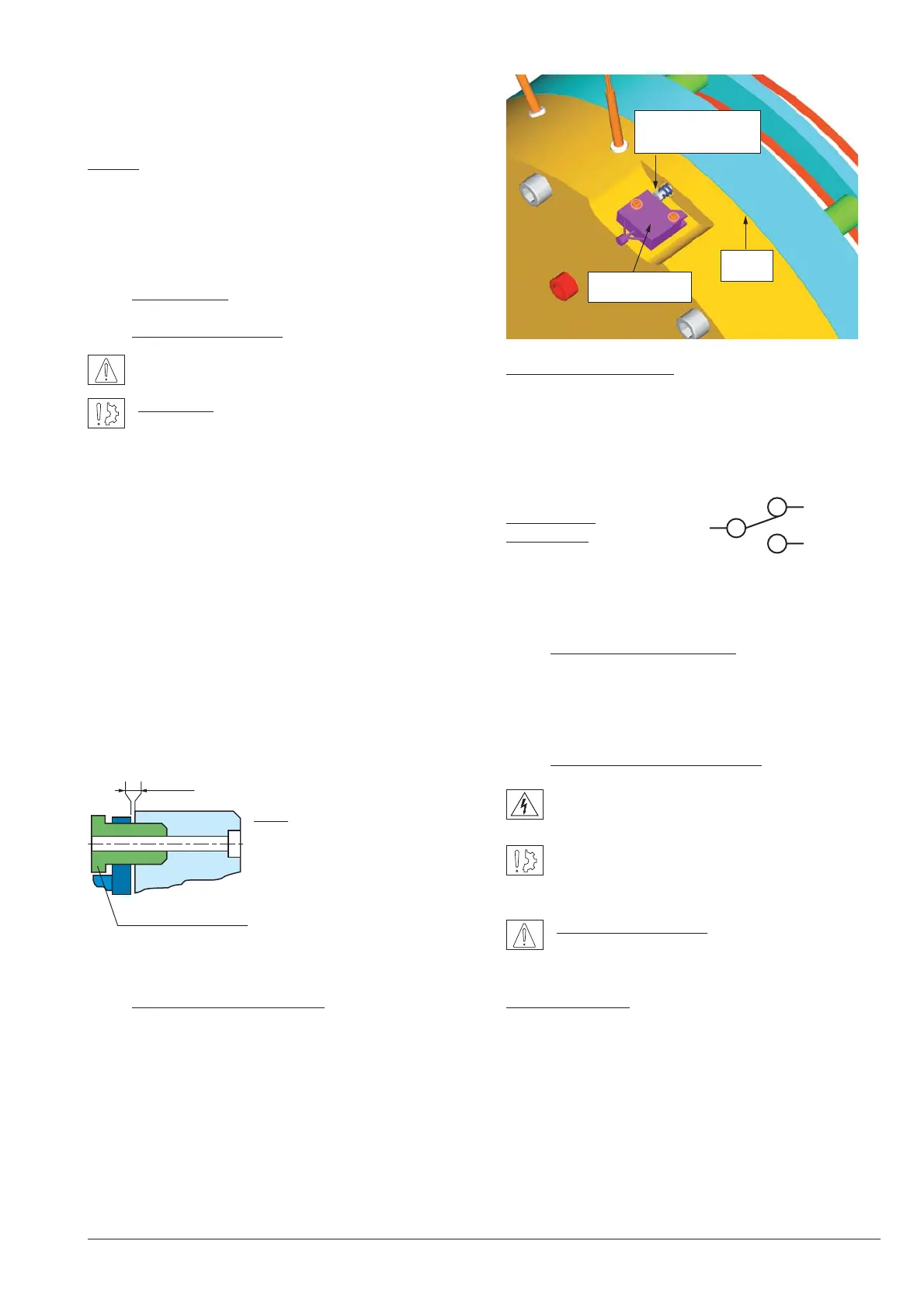
4.2 Adjusting the microswitch
Slide a wedge 0,15mm thick close to the screw between
the front of the inductor and the mobile frame. Switch on
the current and tighten the adjusting screw H M4 (7/flat)
in contact with the microswitch until you reach the
commutation point.
Check that it functions correctly by a few successive draws
and releases.
Operation microswitch
Current range 10 mA min. to 100 mA max. at 24 VDC.
Maximum electrical lifetime of the microswitch ensure only
by switching under resistive load.
Microswitch
connection
When there is no current in the coils (customer’s shaft
braked), the microswitch contacts are in the NC position.
5Raccordement électrique
Brake ERS VAR10 SZ 5000/5000 Warner Electric part
number 1 12 106621 operates on a direct current sup-
ply. Polarity does not affect the way the brake operates.
5.1 Important recommendations
All works on the electrical connections have to be
made with power off.
Make sure that the nominal supply voltage is always
maintained (a lack of power results in a reduced
maximal airgap).
Emergency braking : for emergency braking the
switching OFF must be connected on DC current
side, in order to obtain short engaging time of the brake
Service braking : for service braking, the switching OFF
and the switching ON must be connected on AC current
side, in order to obtain silent switching.
The connecting wires must be thick enough to help prevent
sudden drops in voltage between the source and the brake.
Tolerances on the supply voltage at the brake terminals
+5% / -10% (NF C 79-300).
Fig. 3
Fig. 4