OPERATING MANUAL NBS PRODUCT DESCRIPTION
ThyssenKrupp Aufzugswerke GmbH
Structure
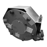
The NBS emergency brake system consists of:
A type-approved electromagnetic disc brake.
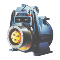
This is mounted directly on the traction sheave or worm drive shaft. It is
located on the opposite side of the traction sheave.
The mounting position of the NBS emergency brake is defined with regard to
the direction of view of the motor towards the gear (arrangement of NBS
emergency brake on left or right). see Fig. 2.1.
An extended traction sheave or worm drive shaft for mounting the brake
on the gear and the necessary additional bore hole in the bearing bracket.
A brake flange for mounting the brake on the gear housing, including set of
seals.
The emergency brake system (NBS) control unit for activation of the
electromagnetic disc brake and connection to the elevator control system.
The circuit for activation of the brake is type-approved and meets the
requirements of EN81-A3.
A monitoring switch mounted on the magnetic brake to monitor the position
of the brake (opened / closed).
An additional safety switch on the speed governor that initiates the brake
operation when the rated speed is exceeded.
The required cable connections for signal forwarding and energy supply.
A schematic overview for connection of the emergency brake system can be
found in Fig. 2.1.
Function principle
Opening: triggered by the run command, the NBS emergency brake system
- which is closed with spring force - opens shortly in front of the shoe brake
fitted on the gear and by opening the shoe brake releases the drive. The
switch state of the NBS emergency brake is indicated when opened by the
indicator lamp on the control unit lighting up.
Closing in the normal mode:
On stopping from a travel movement, the drive switches off first. The
mechanical shoe brake responds and closes the NBS emergency brake
system after a preset delay time.
Closing in the event of emergency stop or power failure:
In all 3 cases, the drive brake and NBS emergency brake respond without a
delay.
(UCM – uncontrolled car movement complying with EN81-A3)
Closing in an emergency situation:
If the speed governor responds to overspeed, the drive switches off and the
drive brake closes. At the same time, the NBS emergency brake is operated
by means of the additional switch on the speed governor.
If the elevator car leaves the door zone with an open door, bridging of the
safety circuit is cancelled by the safety module for the function 'levelling
operation with open door' and / or 'relevelling'. The open safety circuit means
that the NBS contactors drop out and the emergency brake is operated
without delay.