OPERATING MANUAL NBS PRODUCT DESCRIPTION
ThyssenKrupp Aufzugswerke GmbH
2.1.2 Deployment limits and precautions
• To guarantee conformity of the brake in accordance with EU Directive
95/16/EC, the conditions of installation and use must be complied with.
For compliance with the permitted travel speed, the use of a speed
governor complying with EN81-1, Section 9.9, is mandatory. See type test
certificate in the Appendix, chapter 8. The associated ABV no. can be
found in the technical data of the drive.
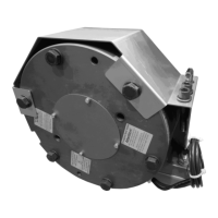
• According to the manufacturer specifications, the NBS emergency brake
system is only permitted for dry operation. Oil, grease and abrasion dust
are to be kept away from the brake, as otherwise the performance
characteristics can change.
• Elevator operation with the brake release screws screwed in is not
possible. Screwing in the screws puts the NBS emergency brake system
out of operation. At the same time, the brake monitoring interrupts the
safety chain.
• The operator must ensure that the setting of the air gap made at the plant
is not changed, thus ensuring faultless release of the brake.
• The NBS emergency brake system is intended for static application as a
parking brake. Dynamic braking is restricted to emergency braking when
the elevator is moving upwards.
Under no circumstances does the brake replace safety systems for
downward operation.
• Any changes to the brake without express approval by the manufacturer
or their representatives lead to loss of warranty entitlements and an
exclusion of liability relevant to conformity.
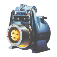
2.2 Function principle of the NBS emergency brake
2.2.1 Indicators in the circuit diagram
2.2.1.1 Location indicators
+TS Elevator control system in the machine room
+T Speed governor in the machine room
+M Drive
+NBS Accessory NBS emergency brake control system