OPERATING MANUAL NBS PRODUCT DESCRIPTION
ThyssenKrupp Aufzugswerke GmbH
Alternatively, the existing switch (Item 3) with one switch contact can be
replaced by a switch with two independent switch contacts. Here, the NBS
emergency brake must be wired in a separate circuit.
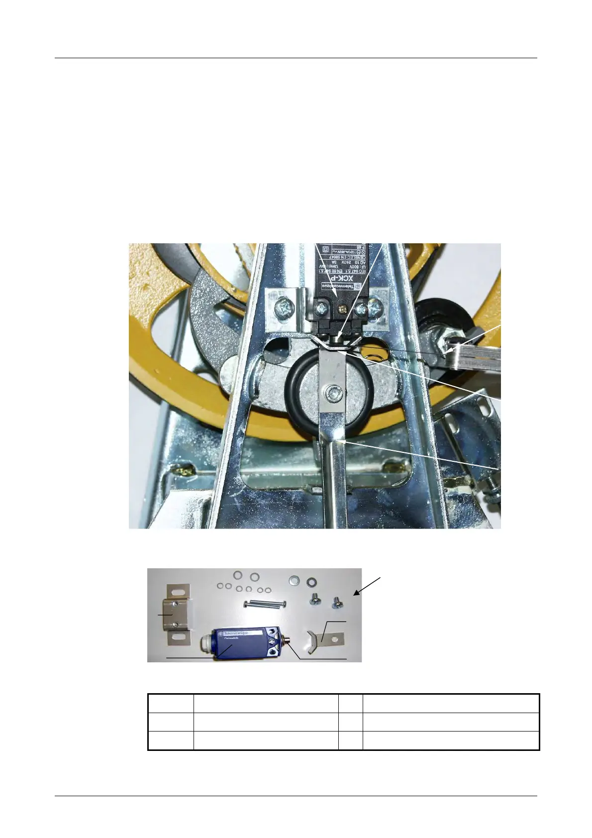
Setting the additional switch:
On retrofitting or replacing the additional switch for the NBS emergency
brake with retrofit kit part number 6023 000 2889 for the ThyssenKrupp
speed governor, the switch is to be set in such a way that the air gap
between the switch tappet and switch cam is 0.3 mm.
See illustration below.
1.5 Safety switch 4.8
Control cam
2.6 Switch tappet 7 Feeler gauge 0.3 mm
3 Retaining plate 9 Locking spring
Representation without safety gear switch
Fig. 2.5.3
Material required to retrofit /
replace the additional
switch.
2
4
1
Fig. 2.5.2