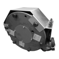
Installation and Operational Instructions
for ROBA-stop
®
-silenzio
®
Type 896.213.30
Sizes 500 – 1800
Chr. Mayr GmbH + Co. KG Tel.: +49 8341 804-0 E079 10 228 000 471
Eichenstraße 1 Fax: +49 8341 804-421 Page 4 of 17
D-87665 Mauerstetten www.mayr.com
Germany E-Mail: info@mayr.com 21/06/2012 TK/HW/GF/SU
Safety Regulations
These Safety Regulations are user hints only and may not be complete!
Ambient Temperature: 0 °C up to + 40 °C
At temperatures of around or under freezing
point, both condensation and the special
characteristics of the linings (lower friction
values at lower temperatures) can strongly
reduce the braking torque.
The user is responsible for taking respective counter-measures,
e.g. selecting brakes with higher nominal braking torques.
Frequent and extensive temperature fluctuations at high
humidity promote the formation of corrosion, which can lead to
seized linings. The brake function must be inspected both once
installation has taken place as well as after longer system
downtimes, in order to prevent the drive starting up against
possibly seized linings. The customer is responsible for
providing a protective cover against contamination caused by
construction sites.
Temperatures of over 70 °C on the brake attachment flange can
have a negative effect on the switching times, the braking
torque levels and the noise damping behaviour.
Appointed Use
This safety brake is intended for use in electrically operated
elevators and goods elevators according to
EN 81-1/1998+A3:2009.
The safety brake corresponds to DIN EN 81, Part 1 [Sections
9.10.2, 9.11.3, 12.4.2.1 (2nd paragraph), 12.4.2.2, and 12.4.2.5]
in its general design and its mode of operation.
Earthing Connection
The brake is designed for Protection Class I. This protection
covers not only the basic insulation, but also the connection of all
conductive parts to the PE conductor on the fixed installation. If
the basic insulation fails, no contact voltage will remain. Please
carry out a standardized inspection of the PE conductor
connections to all contactable metal parts!
Insulation Material Class F (+155 °C)
The insulation components on the magnetic coils are
manufactured at least to insulation material class F (+155 °C).
Protection
(mechanical without cover) IP10: Protection against large
body surfaces and large foreign bodies > 50 mm in diameter.
Water spray coming from any direction may reduce the braking
torque.
(electrical) IP54: Dust-proof and protected against contact as
well as against water spray coming from any direction.
Brake Storage
Store the brakes in a horizontal position, in dry rooms and
dust and vibration-free.
Relative air humidity < 50 %.
Temperature without major fluctuations within a range
from – 20 ° up to +60° C.
Do not store in direct sunlight or UV light.
Do not store aggressive, corrosive substances (solvents /
acids / lyes / salts etc.) near to the brakes.
Special measures are required for longer periods of storage
lasting more than 2 years (please contact the manufacturer).
Handling
Before installation, the brake must be inspected and found to
be in proper condition.
The brake function must be inspected both once installation
has taken place as well as after longer system downtimes, in
order to prevent the drive starting up against possibly seized
linings.
User-implemented Protective Measures:
Please cover moving parts to protect against injury
through seizure.
Place a cover on the magnetic part to protect against injury
through dangerously high temperatures.
Protective circuit: When using DC-side switching, the coil
must be protected by a suitable protective circuit according
to VDE 0580, which is integrated in mayr
®
-rectifiers. To
protect the switching contact from consumption when using
DC-side switching, additional protective measures are
necessary (e.g. series connection of switching contacts).
The switching contacts used should have a minimum
contact opening of 3 mm and should be suitable for
inductive load switching. Please make sure on selection that
the rated voltage and the rated operating current are
sufficient. Depending on the application, the switching
contact can also be protected by other protective circuits
(e.g. mayr
®
-spark quenching unit, half-wave and bridge
rectifiers), although this may of course then alter the
switching times.
Take precautions against freeze-up of the friction
surfaces in high humidity and at low temperatures.