Do you have a question about the TMT XPROG-m and is the answer not in the manual?
Lists the key features and capabilities of the XPROG-m programmer.
Provides specifications like power supply requirements and physical dimensions.
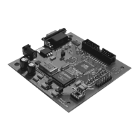
Details the physical layout of the programmer board and its interfaces.
Details connection methods and pinouts for MC68HC05 series microcontrollers.
Explains the connection diagram and signal levels for the MC68HC05E6 microcontroller.
Provides connection details for MC68HC05B6/B8/B16/B32 in PLCC52 package.
Provides connection details for MC68HC05B6/B8/B16/B32 in QFP64 package.
Details connection for MC68HC705B16N/B32 in PLCC52 package.
Details connection for MC68HC705B16N/B32 in QFP64 package.
Connection diagram for MC68HC(7)05X16/X32 in QFP64 package.
Connection diagram and pinout for MC68HC(7)05H12.
Connection diagram for MC68HC(7)05L28.
Connection diagram and signal levels for MC68HC05P3.
Connection diagram and signal levels for MC68HC705P3.
Details on-board and in-circuit programming for MC68HC05V12.
Explains the on-board programming setup for MC68HC05V12.
Details the in-circuit programming connection for MC68HC05V12.
Details connection methods and pinouts for MC68HC08 series microcontrollers.
Connection diagram and signal levels for MC68HC08AS32/AS32A in PLCC52.
Connection diagram and signal levels for MC68HC08AS32/AS32A in QFP64.
Connection diagram for MC68HC08AZ32A.
Connection diagram and signal levels for MC68HC08AS60/AS60A in PLCC52.
Connection diagram and signal levels for MC68HC08AS60/AS60A in QFP64.
Connection diagram and signal levels for MC68HC08AZ60A in QFP64.
Details connection methods and pinouts for MC68HC11 series microcontrollers.
Connection diagram and signal levels for MC68HC11A8/E1/E9/E20 in PLCC52.
Connection diagram and signal levels for MC68HC11A8/E1/E9/E20 in QFP64.
Connection diagram and signal levels for MC68HC11EA9.
Connection diagram and signal levels for MC68HC11F1 in PLCC68.
Connection diagram and signal levels for MC68HC11F1 in QFP80.
Connection diagram and signal levels for MC68HC11K4 in PLCC84.
Connection diagram and signal levels for MC68HC11K4 in QFP80.
Connection diagram and signal levels for MC68HC11KS2 in LQFP80.
Connection diagram and signal levels for MC68HC11KA4 in PLCC68.
Connection diagram and signal levels for MC68HC11KA4 in QFP64.
Connection diagram and signal levels for MC68HC11PH8.
Connection diagram and signal levels for MC68HC11P2.
Connection diagram and signal levels for MC68HC11KW1.
Details connection methods and pinouts for MC68HC(S)12 series microcontrollers.
Connection diagram and signal levels for MC68HC12B32.
Connection diagram and signal levels for MC68HC12BE32.
Connection diagram and signal levels for MC68HC12D60.
Connection diagram and signal levels for MC68HC12DG128.
Connection diagram and signal levels for MC9S12D64 in QFP80.
Connection diagram and signal levels for MC9S12D64 in QFP112.
Connection diagram and signal levels for MC9S12DG256 in QFP80.
Connection diagram and signal levels for MC9S12DG256 in QFP112.
Details on-board programming for the TMS370 family using PLCC adapters.
Details in-circuit programming for the TMS374 family.
Covers on-board and ICP programming modes for M35080 SPI Bus EEPROM.
Information on BMW EWS3 connection using K-Line adapter for data manipulation.
| Category | Motherboard |
|---|---|
| Form Factor | Micro-ATX |
| Memory Slots | 2 |
| Expansion Slots | 1 x PCIe 3.0 x16 |
| Video Outputs | 1x VGA, 1x HDMI |
| Network | 10/100 Mbps Ethernet |