XPROG-m © 2005
TMT
Users manual P/C: 3-001-0001
6
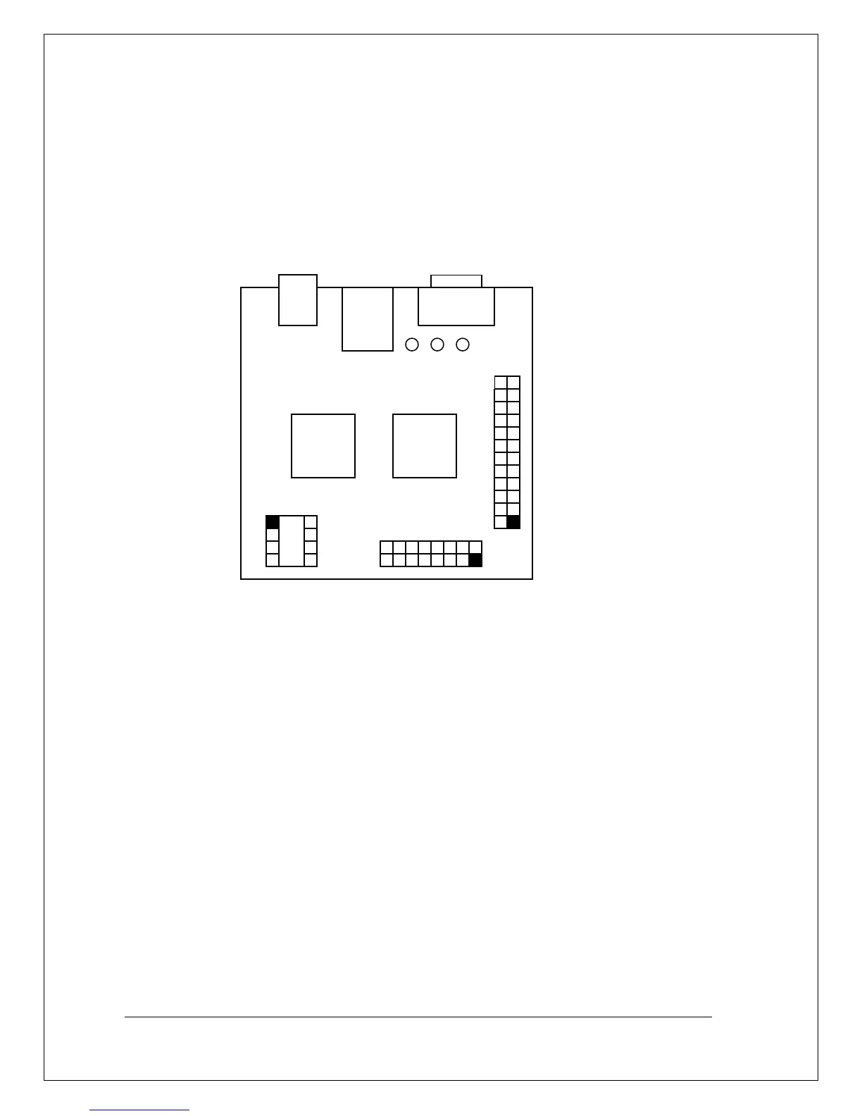
1.3. Programmer board layout
Figure 1 shows the XPROG-m™ Programmer board layout.
XPROG™ connector used both in circuit both on board programming.
Figure 2 and Table 1 shows XPROG™ connector signals and descriptions.
XPROG-m™ connector used only for on board programming and not
described in this section.
RS232
Power
Supply
DIP Socked
XPROG™ connector
Multifunctional
Figure 1. The XPROG-m™ board layout
Led1 Led2 Led3