XPROG-m © 2005
TMT
Users manual P/C: 3-001-0001
7
Table 1. Signals description
Signal name Description
GND Signal and power ground
B0, B1…B7
Protected, high current (±40mA), multifunctional
input/output pins.
+5V/100mA ±5% accuracy, output voltage.
Vcc
PWM regulated, ADC controlled output target supply
voltage. Max. current 100mA
Vpp
PWM regulated, ADC controlled output target
programming voltage. Max. current 100mA
VppR Vpp with series 4.7K resistor
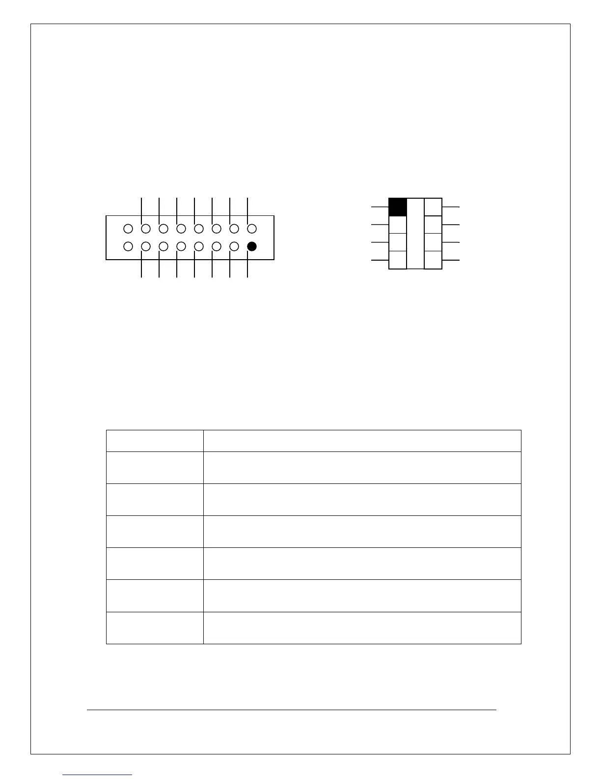
Figure 2. The XPROG™ connector Figure 3. The DIP socked
Vcc
+5V/100ma
B6
B4
B2
B0
GND
VppR
Vpp
B7
B5
B3
B1
GND
B0
B1
B2
B3
B7
B6
B5
B4