1-3
Chapter 1
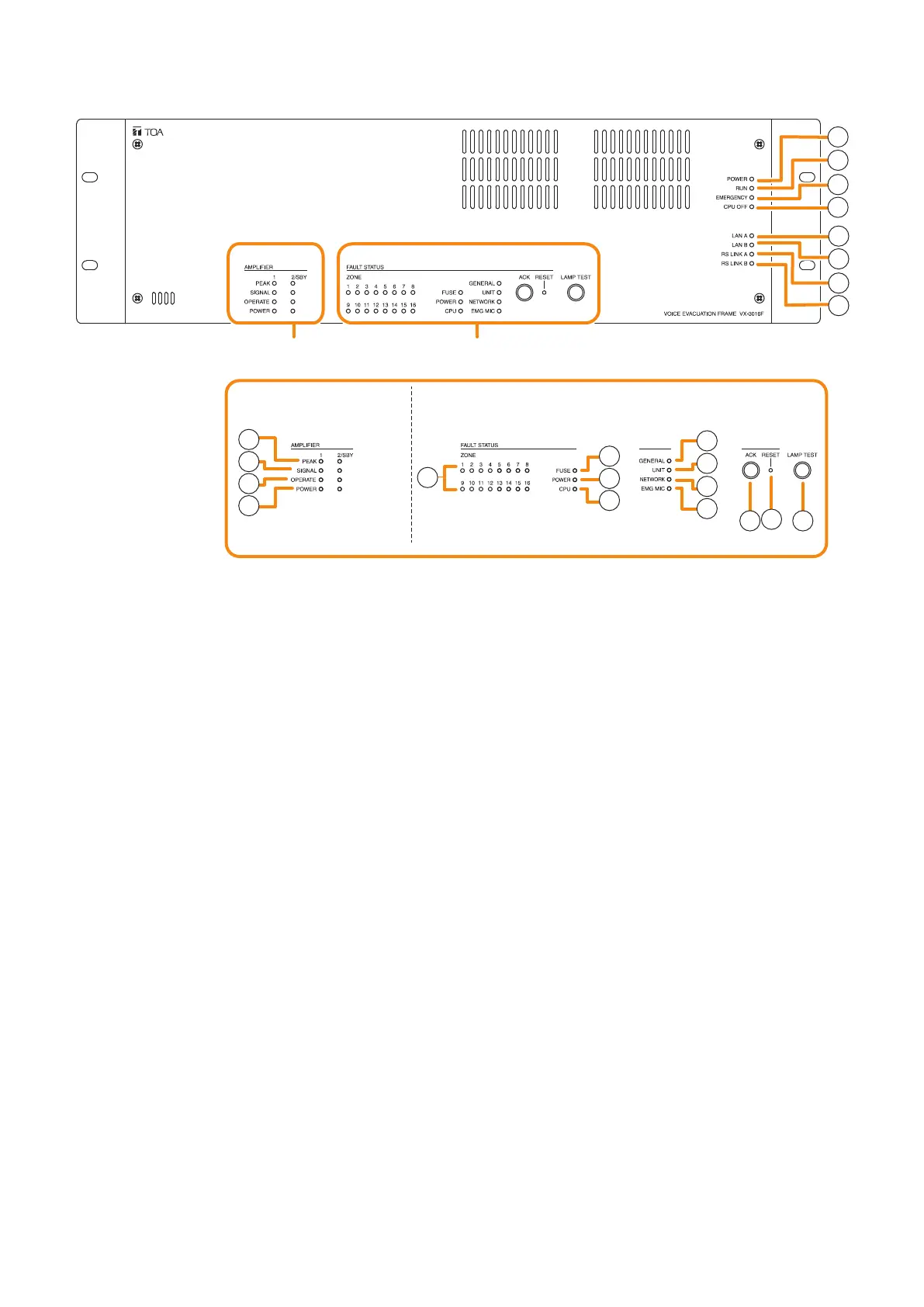
NOMENCLATURE
1. Power indicator (Green)
Lights when the power is supplied.
Flashes in standby state.
2. RUN indicator (Green)
Normallyashescontinuously.Goesoffwhilein
a CPU off state (p. 3-15). Also goes off while in
standby state*
1
.
*
1
A state during power failures or a state that the
unit is internally initialized after power-on
3. Emergency indicator (Red)
Lights when the VX-3000 system is in an
emergency condition or while in a CPU off state
(p. 3-15).
4. CPU off indicator (Red)
Lights while in a CPU off state (p. 3-15).
5. LAN A indicator (Green)
Lights when the LAN link A connector on the
rearpanelisconnected,andashesduringLAN
communications.
6. LAN B indicator (Green)
Lights when the LAN link B connector on the
rearpanelisconnected,andashesduringLAN
communications.
7. RS link A indicator (Green)
Lights when the RS link A connector on the
rear panel is connected, and ashes while
communications are being performed via the RS
link A connector.
8. RS link B indicator (Green)
Lights when the RS link B connector on the
rear panel is connected, and ashes while
communications are being performed via the RS
link B connector.
9.Amplierpeakindicators(Red)
Showtheinputsignalstatetothepoweramplier
whenthepowerampliermoduleisinstalled.
The indicator corresponding to the module slot
port will light if the input signal level exceeds +0.5
dB*
2
.
Itremainsunlitwhennopowerampliermodule
is installed.
10.Ampliersignalindicators(Green)
Showtheinputsignalstatetothepoweramplier
whenthepowerampliermoduleisinstalled.
The indicator corresponding to the module slot
port will light if the input signal level exceeds
-
25
dB*
2
.
Itremainsunlitwhennopowerampliermodule
is installed.
VX-3016F
[Amplifier section] [Fault status section]
9
10
11
12
13
14
15
16
17
18
19
20
21
22
23
1
2
3
5
6
7
8
4
Amplifier section Fault status section
*
2
0 dB = 1 V