Installation
Installing TS-i4 Body Sensor
2-9
P/N: 1049060-01
5. Prepare the welding areas by grinding off the paint around the area where the weld-on plate will
be installed.
6. Position the weld-on plate using clamps or magnets so that it is within two degrees of the plane
of the grouser pads.
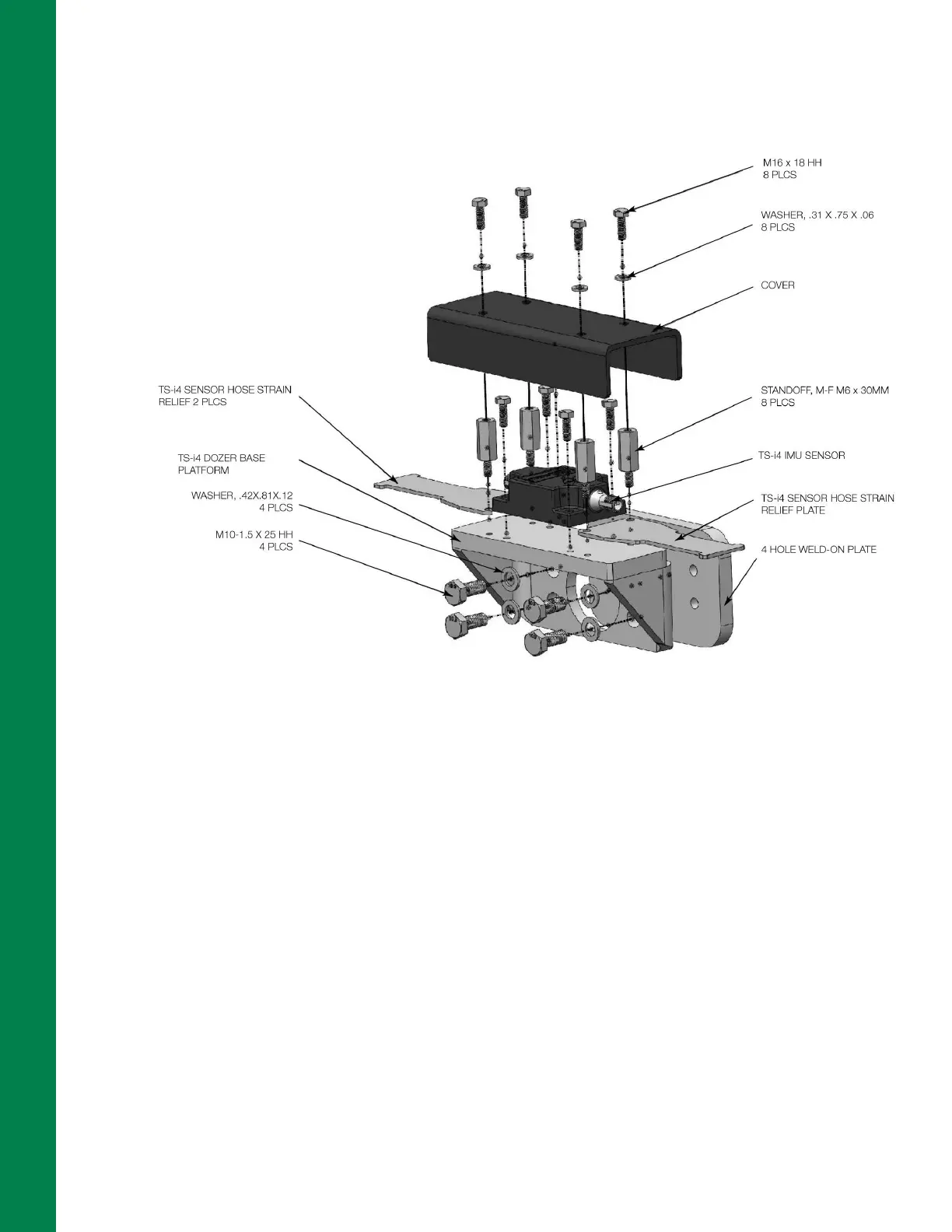
Figure 2-11: TS-i4 Dozer Base Platform (P/N 1040755-01) for TS-i4 Body Sensor Installation
7. Weld the weld-on plate to the dozer body using a suitable welding method (Wire Welding or
Stick Welding). The weld leg size should be 6 mm (1/4 inch), and weld lengths should be at least
50 mm (2 inches).
8. Position the weld-on hose clamps.
9. Weld the weld-on hose clamps to the dozer body using a suitable welding method.
10. Remove any weld slag using a slag hammer or other suitable tool. Scrub off the welds with a
wire brush to prepare them for painting.
11. Paint the weld bracket, weld-on hose clamps, and welds using rust-preventive paint, in a color
that matches the machine.
12. Secure the TS-i4 Dozer Base Platform bracket (P/N 1040755-01) to the weld-on plate
(Figure 2-11) using the supplied M10 bolts and washers.
13. Mount the TS-i4 IMU sensor to the TS-i4 Dozer Base Platform bracket using the two inside
pairs of drilled holes (A) and the supplied hex screws (Figure 2-6 on page 2-4).
14. Use two standoffs to secure each of the strain relief plates to the TS-i4 Dozer Base Platform
bracket using drilled holes (B) as shown in Figure 2-6 on page 2-4.