Installation
Installing TS-i4 Body Sensor
2-10
P/N: 1049060-01
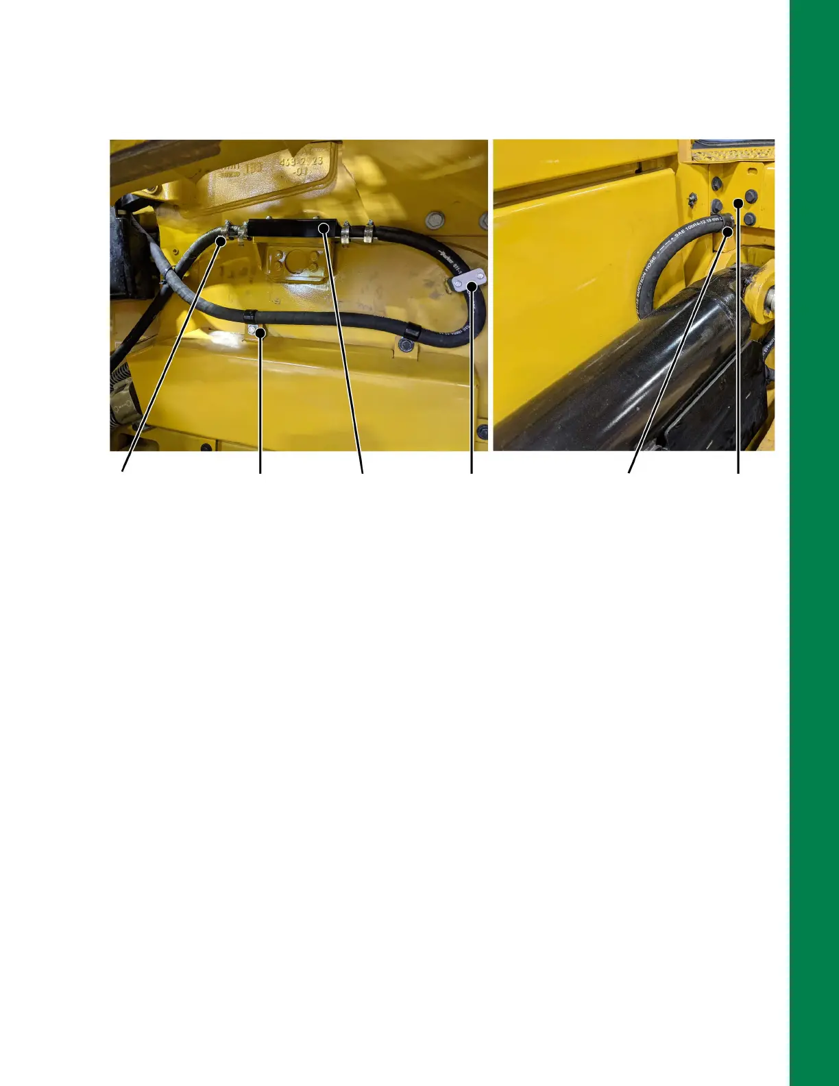
15. Determine the amount of protective hydraulic hose that will be required to protect the M12 cable
from the TS-i4 Body sensor to the machine entrance point (refer to circled area in Figure 2-12).
Figure 2-12: TS-i4 Body Sensor Secured with Protected M12 Cable Routed to MC-X3
16. Cut the hydraulic hose to the required length. Using a grinder or file, clean off any sharp burrs.
17. Feed the M12 cables through the protective hydraulic hoses.
18. Connect the protected M12 cable from TS-i4 C-Frame sensor to TS-i4 Body sensor
(Figure 2-12).
19. Connect the protected M12 cable from TS-i4 Body sensor that will be routed to the MC-X3
(Figure 2-12).
20. Remove the corner bracket (Figure 2-12) and route the M12 cable into the machine and to the
area where the Cable Access Seal will be installed at the back of the cab.
21. Insert a hose clamp under the bottom left bolt of the corner bracket (Figure 2-12). Reinstall the
remaining bolts of the corner bracket.
22. Secure the protected M12 cables to the TS-i4 Body sensor strain relief plates using two hose
clamps for each side (Figure 2-12).
23. Secure the protected M12 cable from the TS-i3 Body sensor with hose clamps and weld-on
hose clamps (Figure 2-12).
Machine Entrance Point
M12 Cable Routing To/From TS-i4 Body Sensor
Protected M12
cable secured
with hose
clamps (4 PLCS)
to strain relief
plates
Hose
clamps
secured
with
existing
bolts
Sensor Cover
Shield
installed after
measurement
& calibration
Weld-on
hose clamp
Hose
clamp
secured
with
existing
bolt
Corner bracket
removed and
replaced to route
M12 to MC-X3
 Loading...
