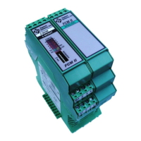
FCM II Installation Guide: 20160419 - Part # 2307
2.6 DEVICE ADDRESS CONFIGURATION
Figure 2.5 shows the locations of I/O, power, and communication status indicators and the location of DIP
switches used to set the module’s serial address. The table below provides the settings for FCM addresses 0 –
31.
Port 0 Status Port 1 Status
Port 2 Status Port 3 Status
Port 4 Status Port 5 Status
Port 6 Status Port 7 Status
TX Status RX Status
FCM 5V Power FCM 12V Output
FCM Address
Dip Switches
Figure 2.5 Module Status, Configuration Setting and Identification

 Loading...