Chapter 6 – Dimensions, Panel Layouts, Wiring
FCM II Installation Guide: 20160419 - Part # 2307
6.3 PANEL ELECTRICAL WIRING SUGGESTIONS
6.3.1 POWER AND COMMUNICATION DISTRIBUTION
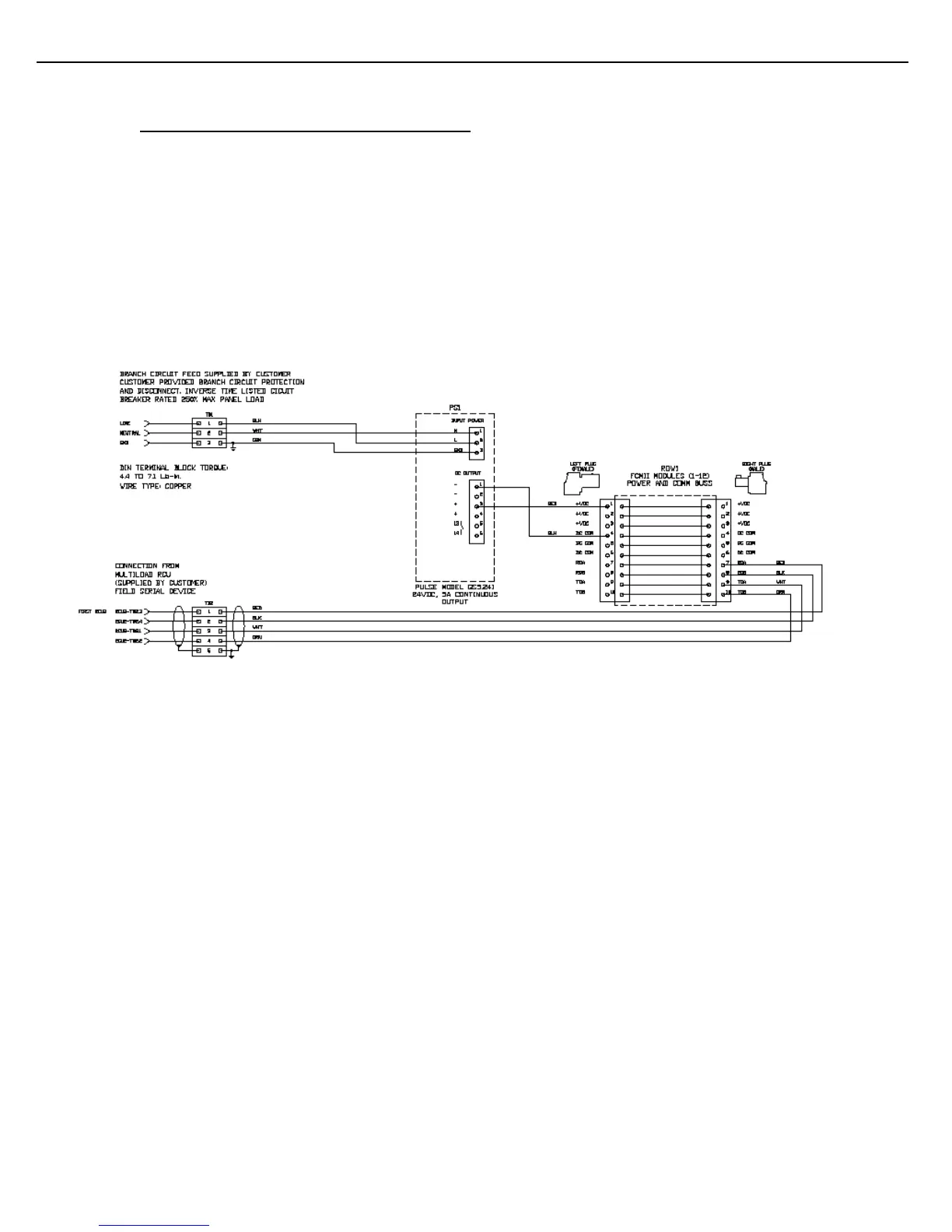
FCM II modules were designed to minimize 24 Vdc input power and serial communication wiring by employing a
distribution buss in the base of the modules. Therefore, considerations only have to be made as to which side of
a DIN rail assembly the power and communication cable should attach (left side female plug or right side male
plug). Note also that star wiring should be avoided, so communication cable extension to adjacent rows ought to
use the opposite end of the joined modules than the end from which communication enters.
Toptech also recommends using one power supply for each DIN rail assembly. See Figures 6.7 to 6.9 for the
various configurations of FCM II power and serial communication wiring schematics.
Figure 6.7 FCM II Power and Serial Communication Panel Wiring: Single Row