Chapter 5 – Troubleshooting
FCM II Installation Guide: 20160419 - Part # 2307
CHAPTER 5 TROUBLESHOOTING
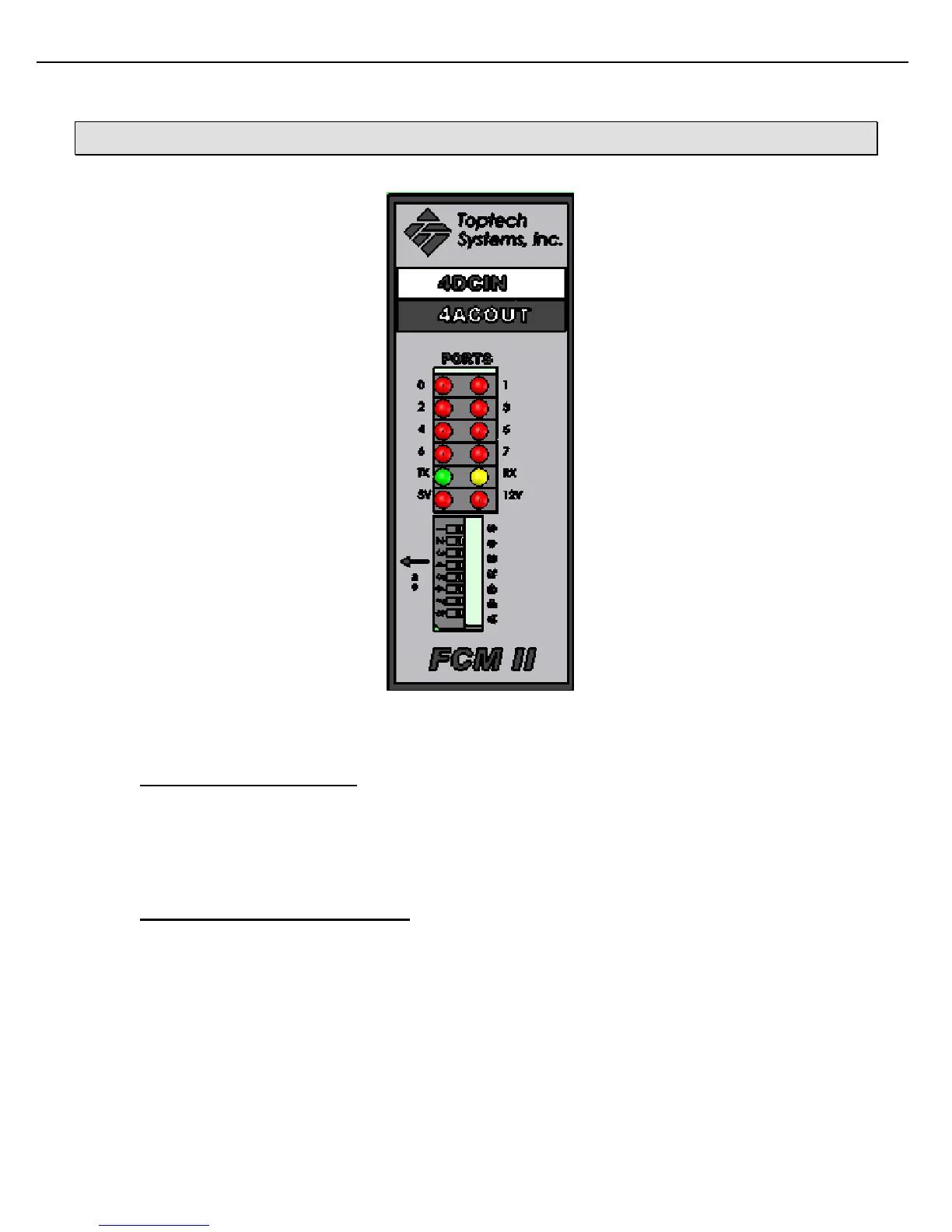
Port 0 Status Port 1 Status
Port 2 Status Port 3 Status
Port 4 Status Port 5 Status
Port 6 Status Port 7 Status
TX Status RX Status
FCM 5V Power FCM 12V Output
FCM Address
Dip Switches
Figure 5.1 FCM II Module Front Panel
5.1 IS THE MODULE POWERED?
All standalone FCM II modules have a front panel LED that shows the power status of its 5V power. In addition,
the 4DCIN/4ACOUT module has a 12V indicator LED showing the status of its onboard 12 Vdc supply used to
power field device dc inputs. The modules must be powered from the BUS rail with a DC voltage source of 19 –
36 Vdc. If required, verify the output voltage and current capacity of the power supply used to power the FCM IIs.
5.2 IS THE MODULE COMMUNICATING?
The quickest check that an FCM II module is communicating with a MultiLoad or other serial device is to look for
the module’s front panel TX LED to flash. The RX LED on all modules will flash when the MultiLoad or other line
master sends a message to any multidropped FCM.
For a more in depth communication status indication, the MultiLoad’s Diagnostic Menu may be used. This menu
is accessible from within the MultiLoad’s configuration mode.
1) Enter program mode by pressing 00000 on the keypad, then press Next key.
2) Select diagnostics from main menu.