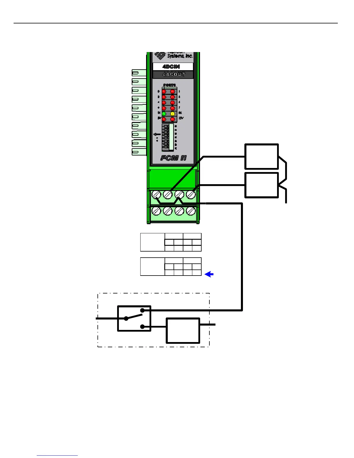
EasyManuals Logo

Toptech FCM II User Manual

Toptech FCM II
50 pages
To Next Page IconTo Next Page
To Previous Page IconTo Previous Page
Page #33 background imageLoading...
Page #33 background image
33
FCM II Installation Guide: 20160419 - Part # 2307
3.2.15 2 OUTPUT AIR ELIMINATOR WIRING
Gnd/Overfill
Switched
Line
N.O. Digital
Valve
Solenoid
N.O. Digital
Valve
Solenoid
Neutral
Port 2 Output
Port 3 Output
Air Purge
Valve
Solenoid
Top Float Switch
Neutral
High
Low
Air Eliminator
Note 2: With only two states returned from the air eliminator, flow must be completely stopped to
purge air.
To purge air by only slowing the rate, a 3 output air eliminator head must be used.
Note 1: When the level drops below Low, the power will be removed from the digital valves, stopping
flow before the air eliminator is completely drained.
A
B
Terminal
Number
In Out In Out
A1 A2 A3 A4
Bottom Side
Bottom Row
Port 0
Port 1
In Out In Out
B1 B2 B3 B4
Bottom Side
Middle Row
Port 2
Port 3
1 2 3 4
Figure 3.16 FCM II Field Wiring: 2 Output Air Eliminator

Table of Contents

Questions and Answers:

Question and Answer IconNeed help?

Do you have a question about the Toptech FCM II and is the answer not in the manual?

Toptech FCM II Specifications

General IconGeneral
BrandToptech
ModelFCM II
CategoryController
LanguageEnglish

Related product manuals