FCM II Installation Guide: 20160419 - Part # 2307
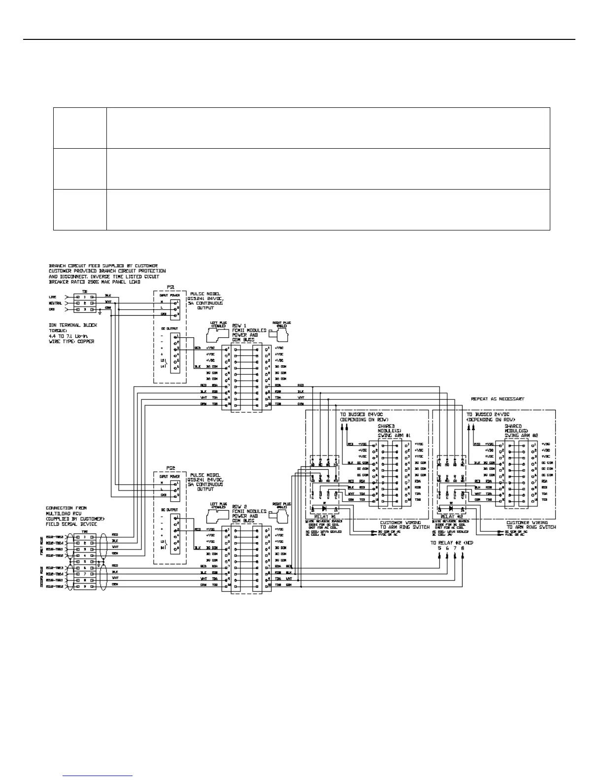
is used to energize or de-energize that relay. Figure 2.7 shows the wiring required to achieve this. The following
guidelines are suggested.
Be aware of device addressing and ensure that duplicate addresses do not exist. The addresses
of shared FCM IIs must not be duplicated in either bay.
Control of the relay coils is to be wired by the customer to the arm ring switch. Note the voltage
available and match it to the relay coil voltage rating. If DC voltage is used, a reverse biased diode
is recommended to snub ringing voltage when the coil opens.
Although star wiring of FCM IIs is discouraged, star wiring of the shared modules is necessary
since switching of shared upstream modules would remove the connectivity of one of the
communication lines from the downstream modules in a daisy chain configuration.
Figure 2.7 Swing Arm Wiring of Shared FCM IIs