FCM II Installation Guide: 20160419 - Part # 2307
CHAPTER 3 FIELD WIRING
3.1 CONNECTION REQUIREMENTS
Although each right angle, four position terminal block is rated for the use of solid or stranded copper 12 to 30
AWG [3.3 to 0.05 mm
2
], Toptech recommends using stranded copper wire 12 AWG to 24 AWG [3.3 to 0.2 mm
2
]
depending on the type of field device. The required screw tightening torque is 5 to 7 Lb-in. [0.6 to 0.8 Nm]. Wires
must be stripped ¼” and inserted into terminal block. Details concerning field wiring terminal assignments are
given later in this chapter.
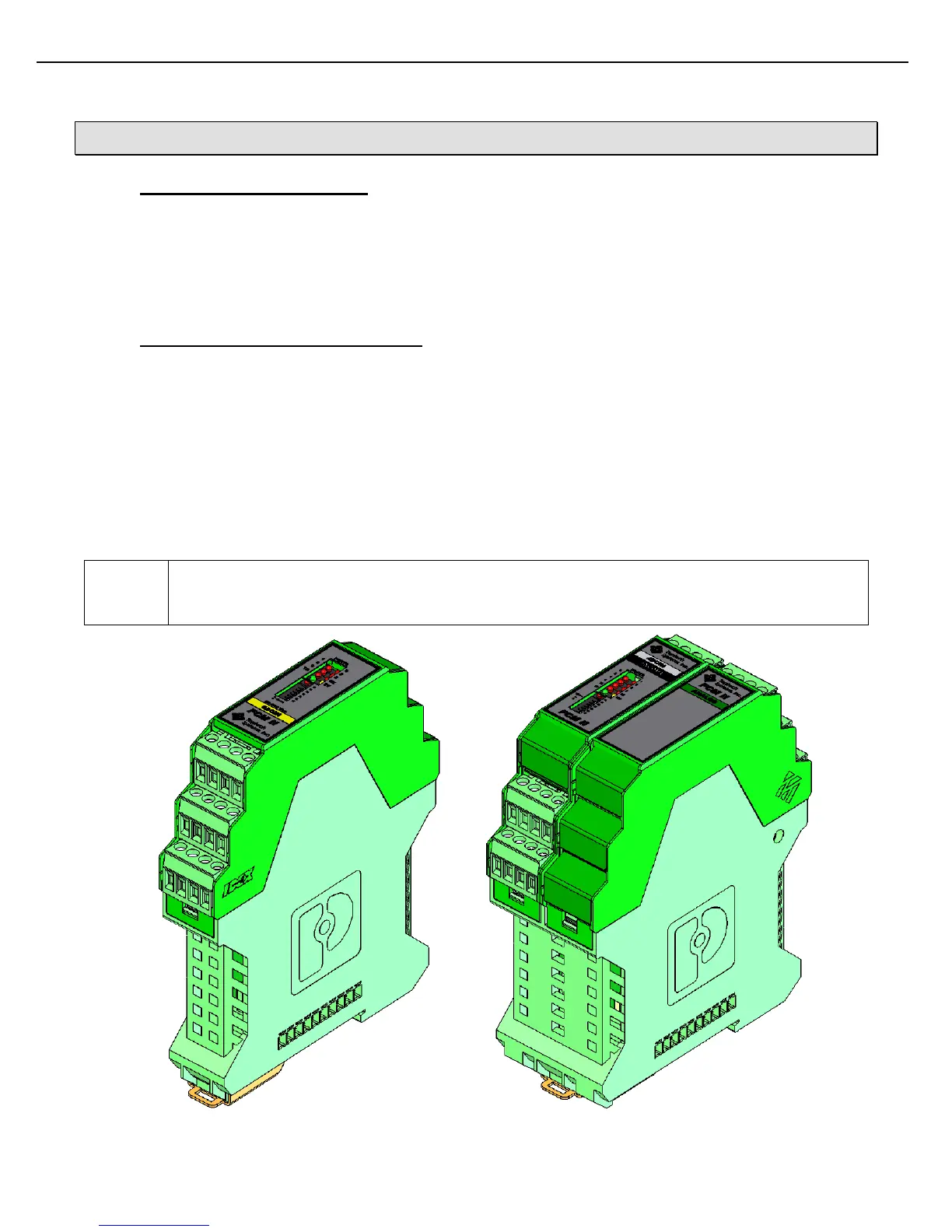
3.2 FCM II FIELD DEVICE CONNECTIONS
FCM II consists of 6 different module types (see Electrical Ratings in section 1.1.1):
1. 4DCIN/4ACOUT: 4 DC Inputs (5-30 VDC), 4 AC Outputs (12-250 VAC),
12 Vdc Power Supply, 167 mA Max
2. 6ACIN: 6 AC Input (90-140 VAC) or (180-250 VAC)
3. 6ACOUT: 6 AC Outputs (12-250VAC)
4. 6DCIN: 6 DC Inputs (5-30 VDC)
5. 6DCOUT: 6 DC Outputs (0-30 VDC)
6. ANALOG/4DCIN/4ACOUT: RTD Input, 4-20mA Input, 4-20mA Out,
4 DC Inputs (5-30 VDC), 4 AC Outputs (12-250 VAC)
Note that the ANALOG board is factory assembled with a 4DCIN/4ACOUT module into a double
wide configuration. It is not possible to use the analog module as a single module, nor should the
analog board be disconnected from its attached 4DCIN/4ACOUT module.