32005 DC BUS
Lables and wire numbers
X+ 302
X- 303
Y+ 304
Y- 305
Z+ 306
Z- 307A+ 324
A- 325
BRAKE RLY+ 328
BRK- 327
BRAKE RLY- 329
BRK+ 326
J2-48VAC L15
J1-48VAC L25
CAP- 300
CAP+ 301
8 A
8 A
8 A
8 A
2 A
8 A
15 A
8 A
503 Optional ATC +
504 Optional ATC -
501 Optional PDB -
502 Optional PDB +
DAUGHTERBOARD
FOR OPTIONAL PDB
F1 = X AXIS
F2 = Y AXIS
F3 = Z AXI
F4 = A AXIS
F5 = DC BRAKE
F6 = MAIN
F7 = PDB
F8 = ATC
F7
F6
F1
F2
F3
F4
F5
F8
S
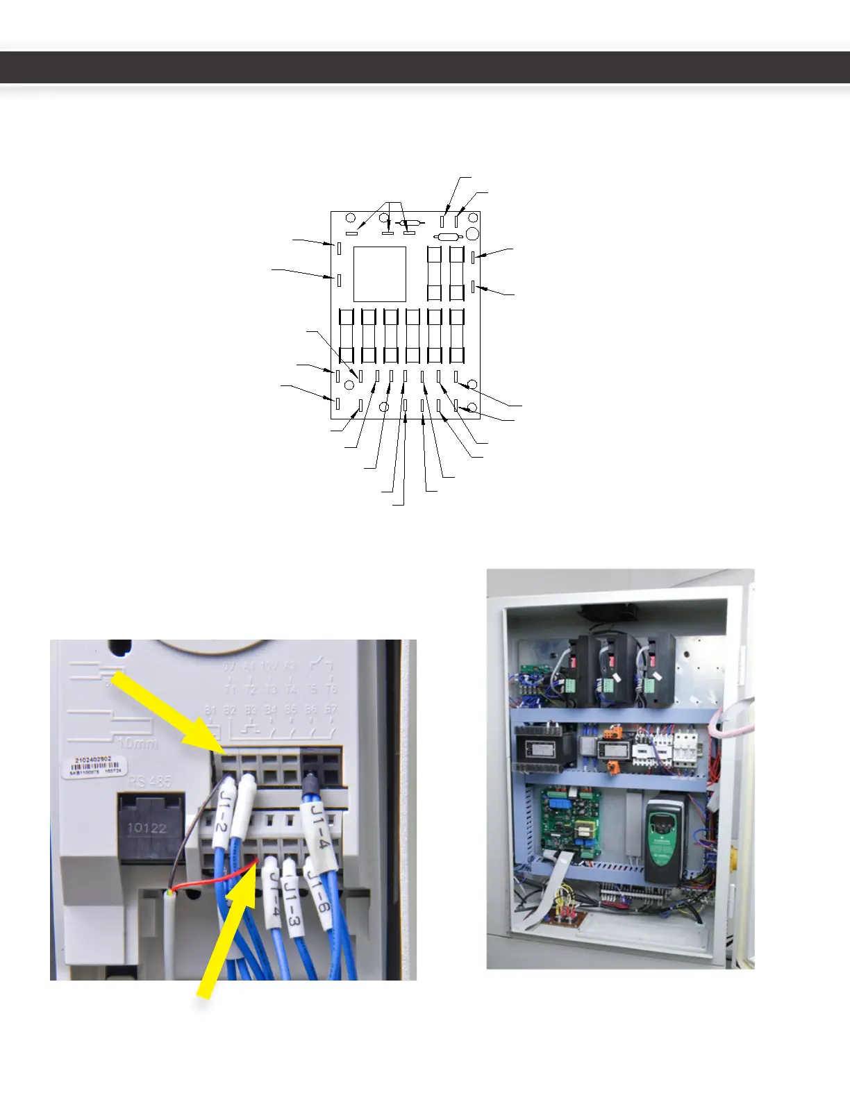
16.InserttheblackandredwiresoftheRJ-11cableinto
posionsT1andB3ontheVFDfor1100machines.To
maketheseconnecons,insertasmallatheadscrew
driverintheholejustabovethewireterminaltoopen
the terminal.
Tidyupthewiresandreplacethecabletraycovers.
Red Wire
to B3
Black Wire
to T1
10
11
UM10081_TTS_ATC_PCNC1100_1013A UM10081_TTS_ATC_PCNC1100_1013A