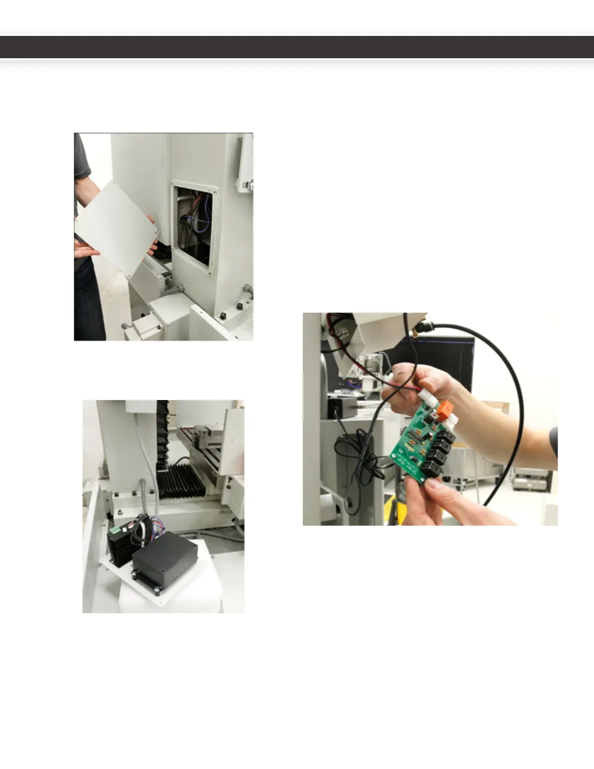
3. ELECTRICAL INSTALLATION
1. Removethefourcolumncoverplatescrewsfrombase
ofcolumnatthebackofthemill.TheZcolumncover
platewillbereplacedwiththeATCcontrolmodule.
Save the screws.
2. LaytheATCcontrolmoduleplatewithsolenoid
sidedownonthechiptrayortheYaxisbearingbox
temporarily.
3. Removethepowerdrawbarelectricalhousing(Zaxis
motorconneconboxcoverplate).
Bar control circuit board.
CircuitboardslabeledRev1.2willneedtobereplaced.In
thiscaseTormachshouldhaveincludedtheupdatedcircuit
boardwithyourATC.
• Toreplaceanold(Rev1.2orearlier)circuitboard,
disconnectandremovetheoldcircuitboard,taking
noteofthelocaonsoftheconnectors.Whilenot
necessary,youmaynditeasiertoremovetheair
linesandthecablecarrieraswell.
• Replacetheolddrawbarboardwiththenewone.
Itiseasiesttoreplacethesolenoidleads(redand
blackwire)beforere-mounngthecircuitboard.The
solenoidleadsgototheoppositesideofboardfrom
otherconnectors.Thisistheonlyconnectoronthat
side(2pinnylon).
ConnecttheblackVFDinterconnectRJ11cable(withthe
spadeterminalends)totheDB1connectoronthepower
drawbarcontrolboard,andtheATCcommunicaonRJ11
cabletotheDB3connectorasshowninthefollowing
gure.
6
7
UM10081_TTS_ATC_PCNC1100_1013A UM10081_TTS_ATC_PCNC1100_1013A