Greensmaster Flex 21 Page 7 – 21 Cutting Unit (Rev. C)
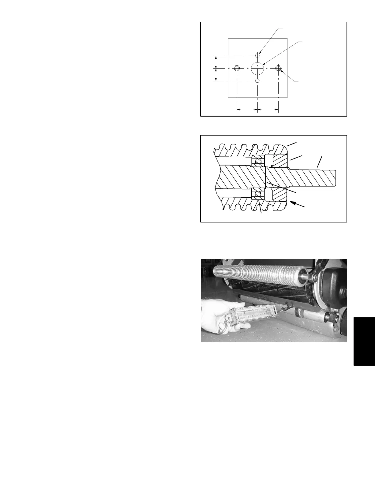
Bearing Installation (Fig. 31)
1. Press bearing into one end of roller. Apply pressure
to outer bearing race only.
2. Install shaft into roller and bearing.
3. Place spiral retaining ring on same end of shaft as
installed bearing.
4. Install second bearing into roller. Apply pressure to
outer bearing race until the outer race contacts shoulder
of roller tube.
5. Position second spiral retaining ring on roller shaft.
6. Install new seals into roller (see Seal Installation).
Seal Installation
1. Lightly grease new oil seal ID and roller shaft sur-
face. Also, apply light coating of grease on outer surface
of installed bearing.
IMPORTANT: Do not use a hammer to install oil
seals in roller as hammer impacts can damage seal.
2. Using a seal installation tool or tubing that contacts
as much of the seal face as possible, press seal into roll-
er. Seal face should be flush with roller surface when
correctly installed (Fig. 31).
3. After seal installation, rotate the roller several times
to allow the seal to seat.
4. After seating the seals, measure the rolling resist-
ance using one of the following procedures:
A. Wrap a string several times around the roller and
connect the end of the string to a spring scale. Pull
the spring scale to identify the rolling resistance of
the roller (Fig. 32). The roller should rotate before the
spring scale registers 6 lbs (2.7 kg).
B. Wedge a 12 point, 15 mm socket on the end of
roller shaft. Using a light–duty, inch–pound torque
wrench, measure the rolling resistance of the roller.
The roller should rotate with less than 6 in–lbs (.68
N–m) resistance.
5. If the rolling resistance of the roller is excessive, light-
ly tap the roller shaft back and forth several times and
follow by again rotating the roller several times. Mea-
sure rolling resistance. If necessary, continue this pro-
cess until the rolling resistance is correct.
Figure 30
.625”
.625”
1.05” 1.05”
.188” dia. (2)
.625” dia.
UNC (2)
Tap 1/4–20
1. Roller shaft
2. Roller
3. Seal
4. Bearing
5. Spiral retaining ring
Figure 31
1
4
3
2
5
SEAL AND ROLLER
SURFACE SHOULD BE FLUSH
Figure 32
Cutting Unit
 Loading...


