Greensmaster Flex 21Traction and Reel Drive System (Rev. C) Page 4 – 6
Traction Drive Belt Adjustment
1. Park mower on a level surface. Make sure engine is
OFF. Remove high tension lead from the spark plug.
2. Remove transport wheels, if installed (see Wheels in
the Service and Repairs section of Chapter 6 – Chassis
and Controls).
3. To check traction drive belt tension (procedure is
identical for both sides of machine):
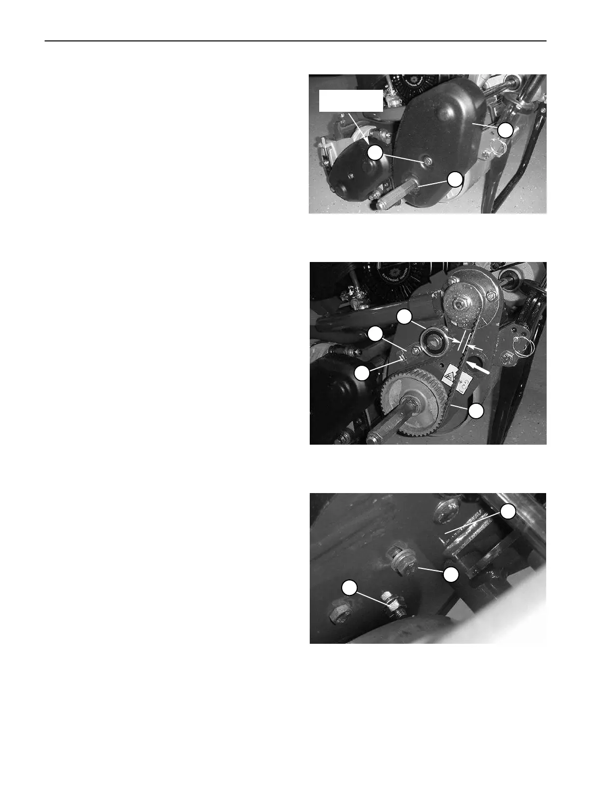
A. Remove cap screw, flat washer, belt cover (Fig.
5), spacer (under cover), and flange nut (Fig. 7) to
expose drive belt.
B. Check belt tension by depressing belt at mid–
span between the pulleys with 3 to 5 lbs (13 to 22 N)
of force (Fig. 6). The belt should deflect 1/4 inch (6
mm).
C. If deflection is correct, continue operation. If
deflection is incorrect, proceed to next step.
4. To adjust traction drive belt tension:
A. On back side of side plate, loosen cap screw that
secures the idler bracket to the side plate (Fig. 7).
B. With a 3/8 inch drive torque wrench, pivot the idler
pulley against the backside of the belt from 35 to 40
in–lb (40 to 46 kg–cm). Do not over tension belt.
Hold idler assembly with the torque wrench and tight-
en idler bracket cap screw to lock adjustment (Fig. 6).
C. Recheck belt tension deflection.
5. Reinstall belt cover by placing the cover with spacer
in position and securing with cap screw, washer, and
flange nut. Tighten cap screw to 100 in–lb (114 kg–cm).
Check that wheel shaft seal position is correct after cov-
er is installed (Fig. 5).
6. Replace transport wheels if they were attached (see
Wheels in the Service and Repairs section of Chapter 6
– Chassis and Controls).
1. Drive belt cover (LH)
2. Cap screw and washer
3. Wheel shaft seal
Figure 5
1
2
3
100 in–lb
(114 kg–cm)
1. Idler pulley
2. Idler bracket
3. Torque wrench position
4. Drive belt
Figure 6
1
3
2
3 to 5 lbs.
4
1/4”
1. Side plate (backside)
2. Idler bracket cap screw
3. Belt cover flange nut
Figure 7
2
1
3
 Loading...


